This thread has been locked.

If you have a related question, please click the "Ask a related question" button in the top right corner. The newly created question will be automatically linked to this question.

Clearing SMBUS_BUS_BUSY in SMBus library.


I have been using SMBus.c library from the tools section for about a month.  Recently, in stress testing, I am getting errors.

After a few thousand reads to 20,000 reads, I get an SMBUS_BUS_BUSY error.  Once that happens, the bus is hung until I restart the application.

I can't find anything about how to clear the BUS_BUSY error in either the SMBus user guide ( SW_TM4C_UTILS_UG-2.1.0.12572) or in the I2C documentation ( SW-TM4C-DRL-UG-2.1.0.12573)

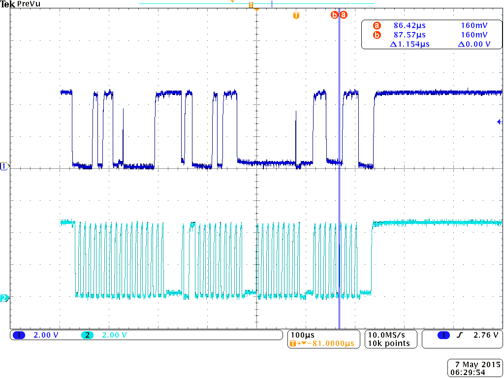
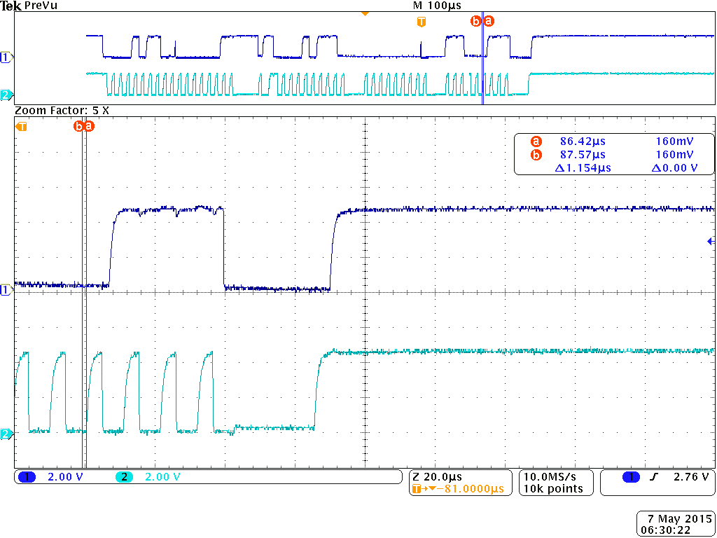
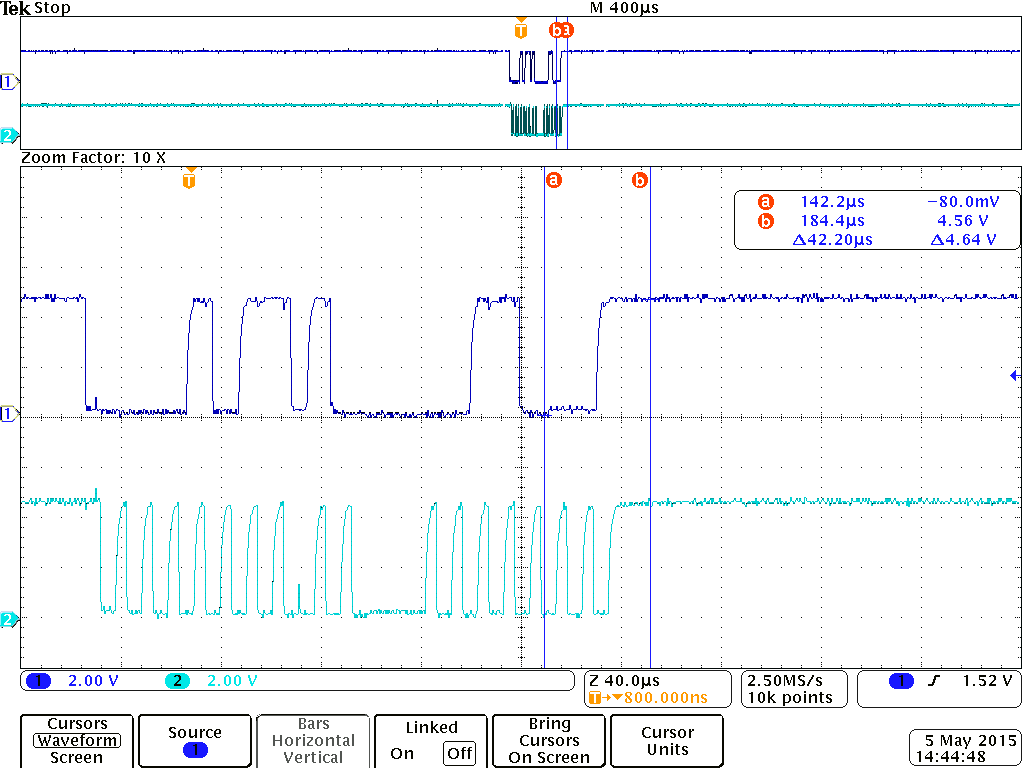
The hardware manual for the TM4C1230 describes the registers and says that this happens when the bus is busy.  Great.  Bus Busy is the time between a start and a stop.  I verified that the signal lines are both high, but I can't guarantee that the stop sequence timing was generated.  I tried ignoring the busy status and issuing a new read command to clear the error. The hardware seems too smart and will not let that command run.

Any suggestions on how to clear this error?

Thanks

  • Hello Dan,

    To understand the issue better, when the hang occurs, what does the I2C_MCS register read as?

    If it does not show BUSBUSY being set, then check the value of the variable flag itself?

    It it does show BUSBUSY, one possible issue may be a line glitch. Enable the Glitch Filter using I2CMCR.GFE=1 and I2CMCR2.GFPW=XX where XX is the equivalent number of system clock time to absorb a glitch of that magnitude.

    Regards
    Amit
  • The MCS register reads 0x7E - not busy, Error, STOP, DATACK, HS, BUSBSY.

    I didn't see a way to clear this error at the register level. There is no traffic on the buss and both lines are inactive (High). MBMON also reports them both as 1.
  • Hello Dan,

    I would suggest the enabling the glitch filter!!!

    Regards
    Amit
  • With the glitch filter, I have not had an error. Thank you.

    However, if it does, how can I clear the error? Worst case, I can reboot, but that seems excessive.
  • Hello Dan,

    For the Master to detect a Bus Busy state, it will see a Start and Stop Condition. if a Glitch is such that a Start condition is detected but not the Stop then it will think the Bus is held. It cannot be cleared without the Stop condition being asserted. Alternatively using 2 other IO's in Open drain mode can be used to artificially create a Start Stop condition which will release the master from this state without having to reset/reboot the device. Also the peripheral can be reset using SysCtlPeripheralReset followed by full configuration to make the master exit this mode w/o the need to reset/reboot the device.

    Regards
    Amit
  • Thanks.  

    This gives me two very good ways to recover.  I need to make this device to run for months without reset. I will add one of these to the recovery mode. M

    The glitch filter may be enough to prevent the deadlock condition.  My hardware has been running much overnight without deadlock.  But, for reliability, if detected, I will use SysCtlPeripheralReset to restart this thread.

  • Hello Dan,

    I2C can be nasty with glitches (something that is accounted for in the specification). In reality the glitches can be way large and hence we added the small-large range of filters with configuration. Hopefully, that is what all is needed.

    Regards
    Amit
  • I am continuing to get the Bus Busy condition on a new version of the PCB.  "Nothing else changed"  

    I am testing by running the same read/write sequence on the bus. I read/modify/write one word register, then read another.  I repeat every 100 ms.   This should not be very demanding.  The system will encounter bus busy within 5 minutes, but probably average more like 100 seconds between failures (1000 cycles, 4000 transactions).  

    I had set the glitch filter to 32.  At 100khz, what are the trade-offs.  It seems with 50mhz clock, 32 clocks would be 640ns. Reasonable, but on the long side.   I tried 16 for glitch filter - not much different - perhaps a little more frequent failure.

    I am monitoring the I2C signals with both a scope and logic analyzer. They look pretty good.  We do have some capacitance in the cables out to my battery.  3.3 Ohms to 5V is not strong enough to meet the 1000ns rise time requirement of the spec.  We tried lower values, but start to run into drive current limits by the battery during clock stretching - the hold clock rises to 400mV - still a zero, but losing margins.

     The failure mode I get is Bus Busy. The MCS also reports IDLE and CLKTO are set.  How can it be BUSY and IDLE at the same time?    I also verified on the scope that there was a valid stop when the busy fault occurred.  

    I implemented bus busy recovery by resetting the I2C peripheral and re-initializing. Recovery works, but I lose data during the prior transfer.  This works every time to reset the device.  

    While the reset approach works, it means that I have lost data, which is very undesirable.  

  • Hello Dan,

    The IDLE is for the controller and not for the Bus. Thus it is OK for the IDLE and BUSBUSY flags to be set. Now as you mentioned that there is a CLKTO also encountered. Can you change the value of the Clock Timeout count and then check.

    Regards
    Amit
  • I moved the CLKTO out to 40ms and still encounter errors.  Usually CLKTO is not set.   But I still get the bus busy error.

    The error seems to be at the eighth bit of the address.  Notice the runt pulse on 8th clock.  We are sending out 0x16, so there runt is where the 8th clock should clock the lsb 0.  It appears to be stepped on.  The next high is where the ACKn should be.  

    We are able to repeat this.  About 1/4 of the failures are caught on the scope (others are after the end of scope capture).  The runt pulses are visible.  Without the bus busy halt,  the runt doesn't appear.

     associated with the 8th bit.  

    I am betting that the issue is firmware induced as it happens in the same position.  I am using the TI SMBus driver from the UTILS package.    I dread debugging through library code.  Do you think this is the next step?  Or is there a hardware explanation? 


    Thanks

  • Hello Dan,

    Or it may be possible that the Slave is seeing a runt pulse and going out of sync!!!

    Regards
    Amit
  • Thanks. We don't think that is it. We have a slight ground differential between the master and the slave and can see about 100 mv difference between low caused by the master and the slave. This is well within the input specifications. Since the grounds appear the same before and after the runt, we believe it is the host side.
  • Hello Dan

    The I2C Master does not cause a Runt condition unless it detects a wrong SCL pulse. Now, as I see in the waveform, there are too may runts appearing during the transaction and I would expect to isolate the cause of the runts on the board. Is there a power trace in the proximity of the device which is switching ON and OFF.

    Secondly, the runt may be seen by the Slave as it may not be having sufficient Glitch filtering and if the 50ns glitch suppression is not there as per the spec then slave may well be out of spec. Also can you see with high resolution the width of the pulses to not exceed the 50ns.

    Regards
    Amit
  • Amit,

    Thank you for all your help so far.

    I think I have something fundamentally wrong with my code.  I wrapped the SMB library into C++ objects and added error counters to the object.  (I have 4 I2C channels and 2 SMB channels in my system).  I do not use globals.  The SMB library "globals" are all encapsulated in the C++ objects as members - usually private members.

    I have been studying the library code in more detail to understand the errors:

    2179904 TotalErrors
    4215636 TotalOperations
    2490 Timeouts
    1277 PeripheralBusy
    48736 BusBusy
    41541 AddressError
    2086489 DataAckError
    PecError
    MasterError
    SlaveError
    1861 OtherErrors
    49148 Bus Resets

    Some of the errors make sense.  The Data Errors are from addressing non-existent registers in my attached SMB battery.  I am not using PEC, so no errors there.  

    But I don't understand the Peripheral Busy.  I am using a thread per I2C channel.  Each thread is a simple linear control loop.  So, I don't understand how the peripheral can be busy.  Bus Resets ~= BusBusy.  So those stats make sense (1.1% Bus Busy errors).

    The battery can issue alerts - but this one doesn't.  It never should become the bus master, so arbitration should never be lost.  I am not sure what Other Errors are.  I may have lumped default counts in there. 

    Given that I have some noise in the I2C signals, should I be attacking the hardware or does this look more like a fault in my wrapper?  

    Thanks

  • Hello Dan

    First things first. Identify the source of the noise as that would clean up a lot of errors that you may have in the wrapper.

    Regards
    Amit
  • Amit,

    Thank you very much. I found the root cause in my code. The TI part did generate the runt pulse due to invalid sequencing of my code. I found that the timeout for a blocking semaphore was set to only 10ms. The remote slave was holding the clock lines low for its setup. After the timeout, bus busy code reset the peripheral.

    I changed the semaphore timeout to 50 ms - twice the allowed TCLK Hold and the bus errors disappeared.

    I erroneously thought the stack would handle error recovery. The example in the documentation hints that error recovery is needed. I was logging errors, but not recovering.

    I am still getting other types of errors that I will need to handle. For example, I get ARB LOST when the battery is sending me unsolicited status information. I had just logged it and moved on to the next message. I am going to add code to wait for the stop condition before trying to send.

    Thanks again for your help. While the code is not yet fully stable, it is 10x better with these simple changes.
  • Hello Dan

    Good info and thanks for getting it logged on the forum

    Regards
    Amit
  • Dan Beadle said:
    3.3 Ohms to 5V is not strong enough to meet the 1000ns rise time requirement of the spec.

    Is the 5V pull-up on the I2C lines applied directly to the Tiva pins, or is a level translator used?

    The Tm4C21230 datasheet says:

    All GPIO signals are 5-V tolerant when configured as inputs
    except for PD4, PD5, PB0 and PB1, which are limited to 3.6 V.
    I am not sure what will happen if the I2C lines, which are open drain bi-directional, are connected to a +5V pull-up.