This thread has been locked.

If you have a related question, please click the "Ask a related question" button in the top right corner. The newly created question will be automatically linked to this question.

Trouble Programming tm4c123gh6pm via LaunchPad

Other Parts Discussed in Thread: ENERGIA

I'm working on a project using TI's Tiva C processor. Specifically, I'm using the tm4c123gh6pmi processor. I've purchased the launchpad board in addition to designing my own board.

My issue is with programming my own board. I'm trying to use the debug JTAG port from the ICDI on the launchpad to program my own board. I've developed my own program with CCS, but am simply trying to upload a "Blinky" (PB3 toggle) program via Energia AND/OR the LM Flash Programmer to my own board to start. LM Flash Programmer always returns an error "Unable to Initialize Target".

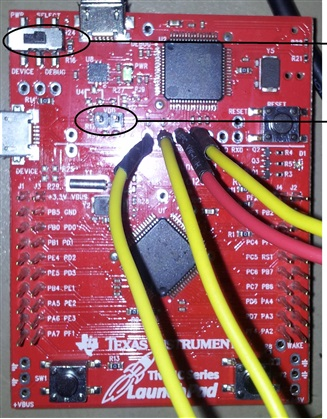
Is there any special steps I need to take with the initial programming of my own board? I'm not sure why my board will not communicate with the ICDI. The "Blinky" program works when I download it to the processor on the launchpad. Here are the steps (slighty different processor, but similar steps should be involved) I am using to use the launchpad as a programmer (EXT DBG left alone, JTAG to JTAG - tx to rx and rx to tx + tck and tms, uart rx to tx and uart tx to rx, plus the reset line).

I've attached the blinky file I am using, along with the schematic of my own board.

Any help would be greatly appreciated! Thanks!

Blink_test.cpp

DevBoardSch.pdfDevBoardTrace.pdf

  • Hello Austin,

    More details on using a LaunchPad as a debugger.

    e2e.ti.com/.../408020

    Please note that TDI on the launchpad is to be connected to the TDI of the end device and the same for TDO. Also the UART RX pin on the debugger is RX pin on the end device and same for UART TX.

    Regards
    Amit
  • Hi Amit, thanks for the quick response. Here are the steps I have taken to program my own board.

    1. Keep the Switch in Debug Mode

    2. Remove the VDD Header

    3. Connect the JTAG Wires
    a. LaunchPad TCK to TCK (PCO)
    b. LaunchPad TMS to TMS (PC1)
    c. LaunchPad TDI to TDI (PC3)
    d. LaunchPad TDO to TDO (PC2)

    4. Connect the UART Wires
    a. LaunchPad TXD to UTX0 (PA1)
    b. LaunchPad RXD to URX0 (PA0)

    5. Connect LaunchPad RESET to RESET (Pin 38 - there is a external 10k pull-up on my board)

    6. Leave LaunchPad EXT DBG unconnected

    7. Connect GND between boards

    8. Open up LM Flash Programmer, select TM4C123G LaunchPad under QuickSet

    9. Select binary file, press Program button.

    10. Receive following error:

    **ERROR**: Unable to initialize target - 0!

    I am unsure what I am doing incorrect. Both boards have power.

    Additionally, in the link you posted there is a .jpg image that you posted. When I try to click on this, I receive an access denied message.
  • Hello Austin.

    Now could there be a problem on the custom board? Can you share the schematics? or better still

    e2e.ti.com/.../374640

    Updated with picture.

    .

    Regards

    Amit

  • Hi Amit, yes my schematics are attached in my first post, labeled DevBoardxxx.
    Yes, I believe I have met all of those requirements.
    Thanks!
  • Hello Austin

    Yes, I see the schematic (as files names were cat, it looked more like trace). Quick Comment after review of schematic

    1. VDDC Cap should not exceed 4.0uF. it is already 6.6uF
    2. RST is connected to a CAP as per the schematic. Not a good idea!!!
    3. Not critical but XOSC1 need not be connected to GND when XOSC0 is already connected to GND
    4. What is the value of Y1?

    Regards
    Amit
  • The value of Y1 = 16 MHz.
    Regarding #2, RST IS NOT connected to a CAP. Do you mean that it should be?
    I can change the value of the VDDc caps, but would that be causing the errors I am seeing?
    Thanks again for your time!
  • Hello Austin

    Please see C13. One leg is connected to RST and another to a connector pin DTR. I would like to see at least this part clear.

    Also now would be a good time to use a scope+DMM to see that when you connect the two boards, is RST high, Core voltage at 1.2V, Supply stable at 3.3V and JTAG signals pulled high when not communicating between the two devices.

    Regards
    Amit
  • Hi Amit.
    I have a small clarification, C13 was simply placed there because I was not sure if I was going to use the reset on the UART or not. There is no capacitor there, I have simply shorted the pads.
    I have done some debugging of JTAG already with with the logic analyzer, and believe the correct signals were high on JTAG as suggested. However, I will retest and check for everything you stated then return with the results. I may or may not have time tonight, but should post by sometime tomorrow.
    Just to confirm, to check the core voltage one checks VDDC, correct?
  • Hello Austin

    Think this is the issue
    c. LaunchPad TDI to TDI (PC3)
    d. LaunchPad TDO to TDO (PC2)

    Should be
    c. LaunchPad TDI to TDI (PC2)
    d. LaunchPad TDO to TDO (PC3)

    Regards
    Amit
  • Hi Amit
    Thanks for all your help. After taking a meter to the board, there were a few issues. First, I was supplying the board with 3.3V, so after the diode going into the on board LDO, the voltage was around 2.4V. I fixed this issue, then additionally correctly wired the JTAG pins and have successfully uploaded my binary file.
    There was an interesting artifact though. I could here some high oscillations coming from what seemed to be the board itself. These pitches would modulate higher when the board was flashing the LED (then go lower when it was not). Any idea what this may be from? Maybe the incorrect cap values on VDDC? I thought I changed them each to 1 uF but accidentally put 0.1 uF so they are quite low. I plan on addressing this issue before moving forward, but wondered if that would be the cause or not.

  • Hello Austin,

    None that I have seen or heard so far. Earlier I had seen some issues due to power supply choke's but not on the LaunchPads.

    Regards
    Amit