This thread has been locked.

If you have a related question, please click the "Ask a related question" button in the top right corner. The newly created question will be automatically linked to this question.

TM4C1294 and RTC DS1307

Hi, 

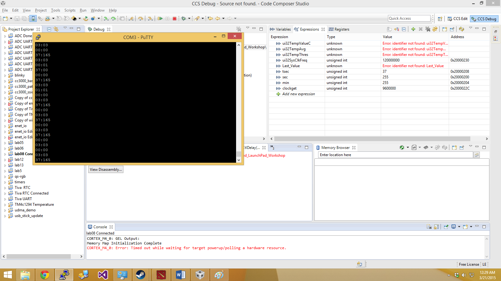
I am trying to interface DS1307 with TM4C1294(connected launchpad). I got it to work in TM4C123 but i am clueless why is it not working in Connected Launchpad. Please help me. The data I'm getting is sometimes jumbled continuously and sometimes only 00:00 is read.

unsigned int sec=3,min=59,tsec=6,tmin=10;

#define SLAVE_ADDRESS 0x68

void SRAMRead(void);
void SRAMWrite(int a,int b);
void initIO();
void ConfigureUART(void);
unsigned char dec2bcd(unsigned char val) ;
unsigned char bcd2dec(unsigned char val) ;

uint32_t ui32SysClkFreq, clockget;
//*****************************************************************************
//
// main()
//
//*****************************************************************************
int
main(void)
{
	unsigned char Last_Value=1;


	ui32SysClkFreq = SysCtlClockFreqSet((SYSCTL_XTAL_25MHZ |
			SYSCTL_OSC_MAIN | SYSCTL_USE_PLL |
			SYSCTL_CFG_VCO_480), 120000000);

	clockget=SysCtlClockGet();

	SysCtlPeripheralEnable(SYSCTL_PERIPH_I2C0);
	SysCtlPeripheralEnable(SYSCTL_PERIPH_GPIOB);

	GPIOPinConfigure(GPIO_PB3_I2C0SDA);
	GPIOPinTypeI2C(GPIO_PORTB_BASE, GPIO_PIN_3);

	GPIOPinConfigure(GPIO_PB2_I2C0SCL);
	GPIOPinTypeI2CSCL(GPIO_PORTB_BASE, GPIO_PIN_2);

	I2CMasterInitExpClk(I2C0_BASE, ui32SysClkFreq, false);

	ConfigureUART();

	//	SRAMRead();

	I2CMasterSlaveAddrSet(I2C0_BASE, SLAVE_ADDRESS , false);
	I2CMasterDataPut(I2C0_BASE, 0);
	I2CMasterControl(I2C0_BASE, I2C_MASTER_CMD_BURST_SEND_START);
	while(I2CMasterBusy(I2C0_BASE));

	I2CMasterDataPut(I2C0_BASE, dec2bcd(sec));
	I2CMasterControl(I2C0_BASE, I2C_MASTER_CMD_BURST_SEND_CONT);
	while(I2CMasterBusy(I2C0_BASE));

	I2CMasterDataPut(I2C0_BASE, dec2bcd(min));
	I2CMasterControl(I2C0_BASE, I2C_MASTER_CMD_BURST_SEND_FINISH);
	while(I2CMasterBusy(I2C0_BASE));

	while(1)
	{
		I2CMasterSlaveAddrSet(I2C0_BASE, SLAVE_ADDRESS , false);
		I2CMasterControl(I2C0_BASE, I2C_MASTER_CMD_BURST_SEND_START);
		I2CMasterDataPut(I2C0_BASE, 0x00);
		I2CMasterControl(I2C0_BASE, I2C_MASTER_CMD_BURST_SEND_FINISH);

		while(I2CMasterBusy(I2C0_BASE));

		I2CMasterSlaveAddrSet(I2C0_BASE, SLAVE_ADDRESS , true);
		I2CMasterControl(I2C0_BASE, I2C_MASTER_CMD_BURST_RECEIVE_START);
		while(I2CMasterBusy(I2C0_BASE));

		sec = I2CMasterDataGet(I2C0_BASE);
		I2CMasterControl(I2C0_BASE, I2C_MASTER_CMD_BURST_RECEIVE_CONT);
		while(I2CMasterBusy(I2C0_BASE));

		min = I2CMasterDataGet(I2C0_BASE);
		I2CMasterControl(I2C0_BASE, I2C_MASTER_CMD_BURST_RECEIVE_FINISH);
		while(I2CMasterBusy(I2C0_BASE));

		//		SRAMWrite(sec,min);


		tsec = bcd2dec(sec)&0x7f;
		tmin = bcd2dec(min);
		if(Last_Value != tsec)
		{
			UARTprintf("%02d:%02d\n",tsec,tmin);
			Last_Value = tsec;
			tsec = 0;
		}
	}
}

void ConfigureUART(void)
{
	SysCtlPeripheralEnable(SYSCTL_PERIPH_GPIOA);

	SysCtlPeripheralEnable(SYSCTL_PERIPH_UART0);

	GPIOPinConfigure(GPIO_PA0_U0RX);
	GPIOPinConfigure(GPIO_PA1_U0TX);
	GPIOPinTypeUART(GPIO_PORTA_BASE, GPIO_PIN_0 | GPIO_PIN_1);
	//	UARTConfigSetExpClk(UART0_BASE, ui32SysClkFreq, 115200,
	//				(UART_CONFIG_WLEN_8 | UART_CONFIG_STOP_ONE | UART_CONFIG_PAR_NONE));

	UARTStdioConfig(0, 115200, ui32SysClkFreq);
	IntMasterEnable();


}

  • I have tried putting while(!(I2CMasterBusy(I2C0_BASE))); together with while(I2CMasterBusy(I2C0_BASE)); but it did not solve the issue.
  • Hello Jeunn

    What about the Pull Up on PB2 and PB3 pins? And have you made sure that the CPU is indeed executing the code and not in a FaultISR

    Regards
    Amit
  • I am using 10k pull up resistor for both PB2 and PB3. The code is executing fine. It is the reading and writing that is producing the problem I think

  • Hello Jeunn,

    I think the polling of the I2CMasterBusy is missing in the following section of the code

    I2CMasterControl(I2C0_BASE, I2C_MASTER_CMD_BURST_SEND_START);
    I2CMasterDataPut(I2C0_BASE, 0x00);
    I2CMasterControl(I2C0_BASE, I2C_MASTER_CMD_BURST_SEND_FINISH);

    Regards
    Amit
  • Hi Amit,

    I have added the line but still nothing..

    		I2CMasterSlaveAddrSet(I2C0_BASE, SLAVE_ADDRESS , false);
    		I2CMasterControl(I2C0_BASE, I2C_MASTER_CMD_BURST_SEND_START);
    		while(I2CMasterBusy(I2C0_BASE));
    		I2CMasterDataPut(I2C0_BASE, 0x00);
    		I2CMasterControl(I2C0_BASE, I2C_MASTER_CMD_BURST_SEND_FINISH);
    		while(I2CMasterBusy(I2C0_BASE));
    

  • Hello Jeunn

    Please do the following

    while(!(I2CMasterBusy(I2C0_BASE)));
    while(I2CMasterBusy(I2C0_BASE));

    Also a screenshot of the transaction when the failure occurs would be very useful

    Regards
    Amit
  • Hi Amit,

    When i Add the while(!(I2CMasterBusy(I2C0_BASE))); it gets suspended.

    Otherwise, the UART is a bunch of random numbers

  • Hello Jeunn

    What i meant was screenshot of the transaction as seen on a scope or a Logic Analyzer when the failure occurs

    Regards
    Amit
  • Like this 

    I apologize for my lack of explanation.

  • Oh... How can i do that? Do i need an oscilloscope?
  • Hello Jeunn

    Yes. And please do attach the corresponding code for the same.

    Regards
    Amit
  • Hi Amit,

    Ok i will try to do it in an hour. Will you be here by then to guide me?
  • Hi Amit,

    Im not sure if this is what you require... i apologize of my low understanding of this.. the blue line is SCL and purple is SDA

  • Sorry.. that was a wrong image..

    the corresponding code is this

    int
    main(void)
    {
    	unsigned char Last_Value=1;
    
    
    	ui32SysClkFreq = SysCtlClockFreqSet((SYSCTL_XTAL_25MHZ |
    			SYSCTL_OSC_MAIN | SYSCTL_USE_PLL |
    			SYSCTL_CFG_VCO_480), 120000000);
    
    	clockget=SysCtlClockGet();
    
    	SysCtlPeripheralEnable(SYSCTL_PERIPH_I2C0);
    	SysCtlPeripheralEnable(SYSCTL_PERIPH_GPIOB);
    	SysCtlDelay(10);
    	GPIOPinConfigure(GPIO_PB3_I2C0SDA);
    	GPIOPinTypeI2C(GPIO_PORTB_BASE, GPIO_PIN_3);
    	SysCtlDelay(10);
    	GPIOPinConfigure(GPIO_PB2_I2C0SCL);
    	GPIOPinTypeI2CSCL(GPIO_PORTB_BASE, GPIO_PIN_2);
    	SysCtlDelay(10);
    	I2CMasterInitExpClk(I2C0_BASE, ui32SysClkFreq, false);
    	SysCtlDelay(10);
    	ConfigureUART();
    
    	//	SRAMRead();
    
    	I2CMasterSlaveAddrSet(I2C0_BASE, SLAVE_ADDRESS , false);
    	I2CMasterDataPut(I2C0_BASE, 0);
    	I2CMasterControl(I2C0_BASE, I2C_MASTER_CMD_BURST_SEND_START);
    //	while(!(I2CMasterBusy(I2C0_BASE)));
    	while(I2CMasterBusy(I2C0_BASE));
    
    	I2CMasterDataPut(I2C0_BASE, dec2bcd(sec));
    	I2CMasterControl(I2C0_BASE, I2C_MASTER_CMD_BURST_SEND_CONT);
    //	while(!(I2CMasterBusy(I2C0_BASE)));
    	while(I2CMasterBusy(I2C0_BASE));
    
    	I2CMasterDataPut(I2C0_BASE, dec2bcd(min));
    	I2CMasterControl(I2C0_BASE, I2C_MASTER_CMD_BURST_SEND_FINISH);
    //	while(!(I2CMasterBusy(I2C0_BASE)));
    	while(I2CMasterBusy(I2C0_BASE));
    
    	while(1)
    	{
    
     		I2CMasterSlaveAddrSet(I2C0_BASE, SLAVE_ADDRESS , false);
    		I2CMasterControl(I2C0_BASE, I2C_MASTER_CMD_BURST_SEND_START);
    //		while(!(I2CMasterBusy(I2C0_BASE)));
    
    		while(I2CMasterBusy(I2C0_BASE));
    		I2CMasterDataPut(I2C0_BASE, 0x00);
    		I2CMasterControl(I2C0_BASE, I2C_MASTER_CMD_BURST_SEND_FINISH);
    //		while(!(I2CMasterBusy(I2C0_BASE)));
    
    		while(I2CMasterBusy(I2C0_BASE));
    
    		I2CMasterSlaveAddrSet(I2C0_BASE, SLAVE_ADDRESS , true);
    		I2CMasterControl(I2C0_BASE, I2C_MASTER_CMD_BURST_RECEIVE_START);
    //		while(!(I2CMasterBusy(I2C0_BASE)));
    
    		while(I2CMasterBusy(I2C0_BASE));
    
    		sec = I2CMasterDataGet(I2C0_BASE);
    		I2CMasterControl(I2C0_BASE, I2C_MASTER_CMD_BURST_RECEIVE_CONT);
    //		while(!(I2CMasterBusy(I2C0_BASE)));
    		while(I2CMasterBusy(I2C0_BASE));
    
    		min = I2CMasterDataGet(I2C0_BASE);
    		I2CMasterControl(I2C0_BASE, I2C_MASTER_CMD_BURST_RECEIVE_FINISH);
    //		while(!(I2CMasterBusy(I2C0_BASE)));
    		while(I2CMasterBusy(I2C0_BASE));
    
    		//		SRAMWrite(sec,min);
    
    
    		tsec = bcd2dec(sec)&0x7f;
    		tmin = bcd2dec(min);
    		if(Last_Value != tsec)
    		{
    			UARTprintf("%02d:%02d\n",tsec,tmin);
    			Last_Value = tsec;
    			tsec = 0;
    		}
    	}
    }

  • Hi Amit,

    Sorry to bother you, did I provide the correct information you require?

    Regards,
    Jeunn
  • Hello Jeunn,

    I was checking the waveform and as I see it, there is a NAK happening and still after that there is a byte being transmitted/received. Can you please confirm if that is a receive or transmit when the NAK happens and then 1's come on the bus?

    Regards
    Amit
  • Hi Amit,

    Is it safe to say that it is a receive because this is the waveform captured as the master is reading from the slave (secs and mins).
    I apologize as my knowledge on this is extremely shallow..

    Regards,
    Jeunn Hao
  • Hi Amit,

    Using breakpoint in the While loop to obtain the waveform, this is the data i get: 

    Am i doing this correctly?

    Thanks for your kind patience..

    Regards,

    Jeunn Hao.

  • Hello Jeunn,

    Yes, you are doing the right thing.

    Regards
    Amit
  • Hi Amit,

    So what would be the reason I am still receiving wrong data from the slave device? How do I solve this problem?
    Regards, Jeunn Hao
  • Hello Jeunn,

    Why is the code being commented.
    // while(!(I2CMasterBusy(I2C0_BASE)));
    Instead did you try putting a SysCtlDelay(3000);

    Also I would need the waveform at the time of failure. So if you know what the failure is going to be then capture the snapshot with a GPIO toggle, such that when the values are unexpected, it will get stuck in a while(1) loop and the last capture will persist. Also please make sure that the pull up strength is good and there are no glitches on the line.

    Regards
    Amit
  • Hi Amit,
    I have commented the line because putting it resulted in the code suspended in it. I will try inserting the delay as suggested.

    Meanwhile, what do you mean by a stronger pull up resistor? I am currently using 10k resistors. Should I increase it?

    The wave forms I shown to you are all failures as they are all incorrect data. Or did I misinterpret "failure "?

    Thanks.

    Regards,
    Jeunn Hao
  • Hello Jeunn,

    If the data is coming from DS1307 then it is an issue with the DS1307 device. If the data is coming from TM4C then what do you expect the actual data to be? That will help me see why TM4C is not sending the correct data.

    Regards
    Amit
  • Hi Amit,

    I have added the while(!(I2CMasterBusy(I2C0_BASE))); and now everything seems to be working fine. Though I am still facing some glitches. For example, removing and reconnecting 5volt Vcc sometimes results in no data being read, as a result, i have to reset Tiva for the counter to start again. (it should keep counting as Vbat is still attached to it.)

    Also, Vbat seemed to stop the counter even when 5 volt Vcc is still connected.

    Though, i am quite satisfied with the results i have obtained. Thanks Amit, you have made me understand I2C better :)

    Regards,
    Jeunn Hao
  • Hello Jeunn

    I am not sure which counter does not start and which 5V is being talked about?

    Regards
    Amit
  • This is the similar problem I am facing. Counter doesn't work
  • Hi,

    Several problems:

    • did you replaced the DS with another chip just to see if previous one is "working" if really worked with TM4C123?
    • how do you connect a +5V device with a 3.3V one? I/O levels are compatible (restriction on TM4C129?)
    • some application notes on Maxim site tell us that the DS1307 chip needs a special register command to be initialized at start-up, since at power-on reset is blocked to avoid battery consumption.

    see tutorial 5791 on this page: www.maximintegrated.com/.../tb_tab2

  • Hello Everyone ,

    I am interfacing TM4C129 Launchpad with DS1307 my code is working fine in updating hour,sec,date,year but min,day and month are not getting updated. I'm verifying the output on putty. Attached is the code.

    Can anyone tell me where I'm going wrong

    //include files
     #include <stdarg.h>
     #include <stdbool.h>
     #include <stdint.h>
     #include "inc/hw_i2c.h"
     #include "inc/hw_memmap.h"
     #include "inc/hw_types.h"
     #include "inc/hw_gpio.h"
     #include "driverlib/i2c.h"
     #include "driverlib/sysctl.h"
     #include "driverlib/gpio.h"
     #include "driverlib/pin_map.h"
     #include "driverlib/uart.h"
     #include "uartstdio.h"
     //Defines for DS1307
     #define SLAVE_ADDRESS 0x68
     #define SEC 0x00
     #define MIN 0x01
     #define HRS 0x02
     #define DAY 0x03
     #define DATE 0x04
     #define MONTH 0x05
     #define YEAR 0x06
     #define CNTRL 0x07

    uint32_t g_ui32SysClock;

     //initialize I2C module 0
     //Slightly modified version of TI's example code
     void InitI2C0(void)
     {
         SysCtlPeripheralReset(SYSCTL_PERIPH_I2C0);
       //enable I2C module 0
       SysCtlPeripheralEnable(SYSCTL_PERIPH_I2C0);
       //reset module
       SysCtlPeripheralReset(SYSCTL_PERIPH_I2C0);
       //enable GPIO peripheral that contains I2C 0
       SysCtlPeripheralEnable(SYSCTL_PERIPH_GPIOB);
       // Configure the pin muxing for I2C0 functions on port B2 and B3.
       GPIOPinConfigure(GPIO_PB2_I2C0SCL);
       GPIOPinConfigure(GPIO_PB3_I2C0SDA);

       // Select the I2C function for these pins.
       GPIOPinTypeI2CSCL(GPIO_PORTB_BASE, GPIO_PIN_2);
       GPIOPinTypeI2C(GPIO_PORTB_BASE, GPIO_PIN_3);


       // Enable and initialize the I2C0 master module. Use the system clock for
       // the I2C0 module. The last parameter sets the I2C data transfer rate.
       // If false the data rate is set to 100kbps and if true the data rate will
       // be set to 400kbps.
       I2CMasterInitExpClk(I2C0_BASE, g_ui32SysClock, false);

     }
     //sends an I2C command to the specified slave
     void I2CSend(uint8_t slave_addr, uint32_t num_of_args, ...)
     {
       // Tell the master module what address it will place on the bus when
       // communicating with the slave.
       I2CMasterSlaveAddrSet(I2C0_BASE, slave_addr, false);

       //stores list of variable number of arguments
       va_list vargs;
       //specifies the va_list to "open" and the last fixed argument
       //so vargs knows where to start looking
       va_start(vargs, num_of_args);
       //put data to be sent into FIFO
       I2CMasterDataPut(I2C0_BASE, va_arg(vargs, uint32_t));
       //if there is only one argument, we only need to use the
       //single send I2C function
       if(num_of_args == 1)
       {
         //Initiate send of data from the MCU
         I2CMasterControl(I2C0_BASE, I2C_MASTER_CMD_SINGLE_SEND);
         // Wait until MCU is done transferring.
         SysCtlDelay(800);
         while(I2CMasterBusy(I2C0_BASE));
         //"close" variable argument list
         va_end(vargs);
       }
       //otherwise, we start transmission of multiple bytes on the
       //I2C bus
       else
       {
         //Initiate send of data from the MCU
         I2CMasterControl(I2C0_BASE, I2C_MASTER_CMD_BURST_SEND_START);
         // Wait until MCU is done transferring.
         SysCtlDelay(800);
         while(I2CMasterBusy(I2C0_BASE));
         //send num_of_args-2 pieces of data, using the
         //BURST_SEND_CONT command of the I2C module
         unsigned char i;
         for(i = 1; i < (num_of_args); i++)
         {
           //put next piece of data into I2C FIFO
           I2CMasterDataPut(I2C0_BASE, va_arg(vargs, uint32_t));
           //send next data that was just placed into FIFO
           I2CMasterControl(I2C0_BASE, I2C_MASTER_CMD_BURST_SEND_CONT);
           // Wait until MCU is done transferring.
           SysCtlDelay(800);
           while(I2CMasterBusy(I2C0_BASE));
         }
         //put last piece of data into I2C FIFO
         I2CMasterDataPut(I2C0_BASE, va_arg(vargs, uint32_t));
         //send next data that was just placed into FIFO
         I2CMasterControl(I2C0_BASE, I2C_MASTER_CMD_BURST_SEND_FINISH);
         // Wait until MCU is done transferring.
         SysCtlDelay(800);
         while(I2CMasterBusy(I2C0_BASE));
         //"close" variable args list
         va_end(vargs);
       }
     }

     //read specified register on slave device
     uint32_t I2CReceive(uint32_t slave_addr, uint8_t reg)
     {
       //specify that we are writing (a register address) to the
       //slave device
       I2CMasterSlaveAddrSet(I2C0_BASE, slave_addr, false);
       //specify register to be read
       I2CMasterDataPut(I2C0_BASE, reg);
       //send control byte and register address byte to slave device
       I2CMasterControl(I2C0_BASE, I2C_MASTER_CMD_BURST_SEND_START);
       //wait for MCU to finish transaction
       SysCtlDelay(800);
       while(I2CMasterBusy(I2C0_BASE));
       //specify that we are going to read from slave device
       I2CMasterSlaveAddrSet(I2C0_BASE, slave_addr, true);

       I2CMasterControl(I2C0_BASE, I2C_MASTER_CMD_BURST_RECEIVE_START);
       //specify that we are going to read from slave device

       //wait for MCU to finish transaction
       SysCtlDelay(800);
       while(I2CMasterBusy(I2C0_BASE));
              //send next data that was just placed into FIFO
              I2CMasterControl(I2C0_BASE, I2C_MASTER_CMD_BURST_RECEIVE_CONT);
              //specify that we are going to read from slave device
              // Wait until MCU is done transferring.
              SysCtlDelay(800);
              while(I2CMasterBusy(I2C0_BASE));
          I2CMasterControl(I2C0_BASE, I2C_MASTER_CMD_BURST_RECEIVE_FINISH);
          //specify that we are going to read from slave device
             //wait for MCU to finish transaction
             SysCtlDelay(800);
             while(I2CMasterBusy(I2C0_BASE));
       //return data pulled from the specified register
       return I2CMasterDataGet(I2C0_BASE);
     }
     //convert dec to bcd
     unsigned char dec2bcd(unsigned char val)
     {
          return (((val / 10) << 4) | (val % 10));
     }
     // convert BCD to binary
     unsigned char bcd2dec(unsigned char val)
     {
      return (((val & 0xF0) >> 4) * 10) + (val & 0x0F);
     }

     //Set Time
     /*void SetTimeDate(unsigned char sec, unsigned char min, unsigned char hour, unsigned char day, unsigned char date, unsigned char month,unsigned char year)
     {

          I2CSend(SLAVE_ADDRESS,8,SEC,dec2bcd(sec),dec2bcd(min),dec2bcd(hour),dec2bcd(day),dec2bcd(date),dec2bcd(month),dec2bcd(year));
     }*/
     void SetHour(unsigned char hour)
      {
         unsigned char h;
         h=dec2bcd(hour);
           I2CSend(SLAVE_ADDRESS,2,HRS,h);

      }
     void SetMinute(unsigned char min)
     {
         unsigned char m;
         m=dec2bcd(min);
          I2CSend(SLAVE_ADDRESS,2,MIN,m);

     }

     void SetSec(unsigned char sec)
      {
         unsigned char s;
         s=dec2bcd(sec);
           I2CSend(SLAVE_ADDRESS,2,SEC,s);

      }
     void SetDay(unsigned char day)
      {
         unsigned char d;
         d=dec2bcd(day);
           I2CSend(SLAVE_ADDRESS,2,DAY,d);

      }
     void SetDate(unsigned char date)
      {
         unsigned char d;
         d=dec2bcd(date);
           I2CSend(SLAVE_ADDRESS,2,DATE,d);

      }
     void SetMonth(unsigned char month)
      {
         unsigned char m;
         m=dec2bcd(month);
           I2CSend(SLAVE_ADDRESS,2,MONTH,m);

      }
     void SetYear(unsigned char year)
      {
         unsigned char y;
         y=dec2bcd(year);
           I2CSend(SLAVE_ADDRESS,2,YEAR,y);

      }
     void SetControl(unsigned char control)
      {

           I2CSend(SLAVE_ADDRESS,2,CNTRL,dec2bcd(control));

      }
     //Get Time and Date
     unsigned char GetClock(unsigned char reg)
     {
          unsigned char clockData = I2CReceive(SLAVE_ADDRESS,reg);
          return bcd2dec(clockData);
          //return clockData;
     }
     void ConfigureUART(void)
     {
            // Enable the GPIO Peripheral used by the UART.
            SysCtlPeripheralEnable(SYSCTL_PERIPH_GPIOA);
         // Enable UART0.
            SysCtlPeripheralEnable(SYSCTL_PERIPH_UART0);

            // Configure GPIO Pins for UART mode.
            GPIOPinConfigure(GPIO_PA0_U0RX);
            GPIOPinConfigure(GPIO_PA1_U0TX);
            GPIOPinTypeUART(GPIO_PORTA_BASE, GPIO_PIN_0 | GPIO_PIN_1);

            // Initialize the UART for console I/O.
            UARTStdioConfig(0, 115200, g_ui32SysClock);

     }
     void main(void)
     {

          // Set the clocking to run directly from the external crystal/oscillator.
         g_ui32SysClock = SysCtlClockFreqSet((    SYSCTL_XTAL_25MHZ |
                                 SYSCTL_OSC_MAIN   |
                                 SYSCTL_USE_PLL       |
                                 SYSCTL_CFG_VCO_480), 120000000);

            //initialize I2C module 0
            InitI2C0();
            ConfigureUART();
            //SetTimeDate(36,55,10,4,27,10,16);
            SetSec(00);
            SetMinute(46);
            SetHour(11);
            SetDay(2);
            SetDate(8);
            SetMonth(11);
            SetYear(16);
            SetControl(0x13);
            unsigned char sec,min,hour,day,date,month,year,control;


            while(1)
            {
                sec = GetClock(SEC);
                min = GetClock(MIN);
                hour = GetClock(HRS);
                day = GetClock(DAY);
                date = GetClock(DATE);
                month = GetClock(MONTH);
                 year = GetClock(YEAR);
                 control = GetClock(CNTRL);

                 UARTprintf("%02d:%02d:%02d \n%02d %02d/%0d/%02d\n \n%02d\n",hour,min,sec,day,date,month,year,control);

                SysCtlDelay(g_ui32SysClock);
            }

     }

  • Hello Rohit,

    Did you compare the output from the DS1307 with the I2C waveform as captured on a scope or Logic Analyzer?

    Also I would advise you to search DS1307 as the keyword on the forum search to see similar attempts in the past have succeeded.
  • Dear Amit,
    My clock is counting and updating fine. Just the minute, day and month values are appearing absurd although internally the clock is working fine. I see absurd values for minute, day and month. Can you help me with this specific problem?

    Regards,
    Keyshav
  • Hello Rohit,

    Do you have a log of the values from the first time it is set in the RTC device followed by a subsequent read?

    Also without code and the capture of the I2C on the IO pins, it would not be possible for me to tell what is going wrong!!!

    That is why I suggested checking other example codes. Also do make sure that the DS1307 is correctly wired and using the correct clock.