This thread has been locked.

If you have a related question, please click the "Ask a related question" button in the top right corner. The newly created question will be automatically linked to this question.

Ethernet Interrupts never occur in a custom board of TM4C1294

Hi,


I am developing on a custom board of TM4C1294+lwip1.4.1+freeRTOS+ccs6.1.

The Ethernet is used for socket communication with a server, and the communications modules run well in EK-TM4C1294.

However, the custom board,same schematic as ek board, not even detects the Ethernet interrupt. It does not call `lwIPEthernetIntHandler` defined in startup_ccs.c as well as` lwIPInterruptTask` in lwiplib.c.


I checked some registers associated with Ethernet in the custom board, but I have not found any problems in registers. Unlike EK board, EMAC_TXCNTGB, TXOCTCNTG, RXCNTGB, RXCNTGUNI never update any values since the Ethernet Interrupts never occur in the custom board. Other than them, the values of register related with EMAC are same between Ek board and custom one. (also RCGCEMAC = 1 and RCGCEPHY=1, PREPHY=1, PREMAC=1,)

So does it look like hardware issues?.


Thanks,

Jin

  • Hello Jin,

    Sounds like one. However before making any comments, can you first check if with the SW for EK-TM4C1294 for LwIP does the custom board work?

    Regards
    Amit
  • Hi Amit,

    The new custom board is designed based on TM4C1294 but different usages of GPIO ports. However, Ethernet(EN0TX,RX...) is not configured by any gpio ports, so it should not be a matter I believe.

    I just tested enet_lwip for both EK and custom board, and the example did not work on the custom board. Like I said, the communication codes in my project work well in EK board just like enet_lwip.

    If the problems come from hardware, how can I verify where the problems are from? since the components associated with Ethernet is so tiny. It is even hard to use scope.

    thanks,
    Jin

  • Hello Jin

    Schematic's please... As we need to check the ethernet section. Also can you make sure that it is not a Bus Fault or some other configuration in SW which does not enable Ethernet Interrupt parallely.

    Regards
    Amit
  • Hi Amit,

    I am not the office until Tuesday next week, so as I get back I will response.

    Thanks,

    Jin

  • Hi Amit,

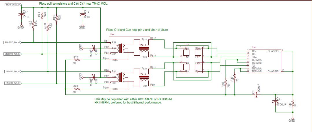
    I was given only a paper schematic, but it is identical with Ethernet schematic of TM4C

    When it comes to bus, the custom board is built as a PCB just like TM4C populated by TI, so I am not sure how you guys check buses if they work well or not if the lines and components are so tiny. Also the custom board does not have breadboard connection header.

    As I tested  the program that I work on TM4C, lwIPInterruptTask() and lwIPEthernetIntHandler() were called alternately in order to enable/disable Ethernet interrupt, but those two functions were not called on the custom board.

    If none of Ethernet frames is detected by the custom board, so no interrupt happens right?

    Thanks,

    Jin

  • Hello Jin,

    I would like to see the full "paper" schematic. Since that is the source of the custom board.

    Regards
    Amit
  • Hi Amit,

    Here is the schematic, and the schematic will be deleted as you read.

    Thanks,

    Jin

  • Hello Jin,

    I went through the schematics and here are my observations

    1. Why is a 16MHz crystal connected to Hibernate? Hibernate crystal is 32768Hz (32KHz).

    The only reason I see for the Ethernet not to work is that the Y1=25MHz is not 25Mhz but some other frequency crystal. Can you measure the frequency of oscillation?

    Regards
    Amit
  • Hi Amit,

    There is an another guy who drew the schematic, and he seems to copy the clock configuration from LM3S9B to TM4C.

    Yeah, I am suspicious about 25Mhz clock for Ethernet MAC/PHY. I don't have an oscilloscope now, so as I get it I will test it.

    Thanks,
    Jin
  • Hi Amit,

    I tried to measure the frequency of oscillator, but the chip is so tidy, and it is already mounted on the custom pcb.

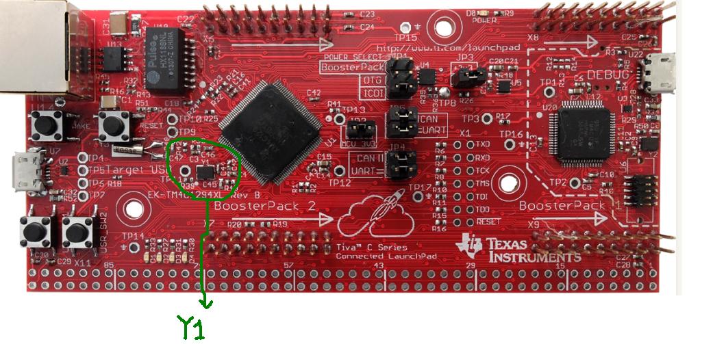
    Even with TM4C board I am not sure how I can measure the frequency of OSC(Y1 below) directly?

    Thanks,

    Jin

  • Hello Jin,

    You can measure the OSC0 at C44 on the LaunchPad. Another alternative would be to have a simple code to toggle a GPIO Pin in a while loop with System Clock Configured to 120MHz when running from PLL. Then flash the same code to your custom board and measure the GPIO toggle rate. If the main crystal is working correctly at 25MHz then it should be the same.

    Regards
    Amit
  • Hi Amit,

    I measured the frequency at PORT A/Pin 5, and gave me a same rate.


     while(1)
        {
            //
            // Turn on D1.
            //
            LEDWrite(CLP_D1, 1);
            GPIOPinWrite(GPIO_PORTA_BASE, GPIO_PIN_5, 0x00);
            //
            // Delay for a bit.
            //
            SysCtlDelay(g_ui32SysClock / 10 / 3);
    
            //
            // Turn off D1.
            //
            LEDWrite(CLP_D1, 0);
            GPIOPinWrite(GPIO_PORTA_BASE, GPIO_PIN_5, GPIO_PIN_5);
            //
            // Delay for a bit.
            //
            SysCtlDelay(g_ui32SysClock / 10 / 3);
        }

    It seems 25Mhz Xtal works well although Y2 values are wrong.

    Thanks,

    Jin

  • Hello Jin,

    Very strange. There is nothing else in the schematic that I could put my finger except the 16MHz crystal. I would suggest either replace it or for the moment remove and GND XOSC0 pin.
    Since the Main Oscillator is now 25MHz as confirmed by your code (GPIO toggle), I am not sure why this issue is occurring. Also can you verify if LINK is getting established by the PHY. W/O having the board it is tough to debug remotely.

    Regards
    Amit
  • Hi Amit,

    I will ask the guy who drew the schematic to change components; however, I am not sure how I can verify "LINK" established by PHY.

    Unlike the schematic, LD2,3,4 are not on the custom board. Therefore, Ethernet Link is not detected by LED now.

    Is that you talk about?

    Thanks,
    Jin
  • Hello Jin,

    LD2-LD4 can be mounted though? The PHY also notifies in the code when LINK is established. It is there in lwiplib.c as the function lwIPLinkDetect

    Regards
    Amit
  • Hi Amit,

    The custom board was populated already, so I will ask to have LEDs for the later version of board.

    However, the custom board connected to one of ports of a "Dell Switch" never blinks "port LED" on the switch unlike connecting with "EK-TM4C1294" Launchpad where "port LED" on the switch blinks as communicating between Server and Launchpad.

    In lwIPLinkDetect(), the below code always gives "0" as testing the custom board.

    bHaveLink = MAP_EMACPHYRead(EMAC0_BASE, 0, EPHY_BMSR) & EPHY_BMSR_LINKSTAT;

    As a result, it always reaches to "return;" and never updates the Link status(initially g_bLinkActive =0) and executes further codes.

        if(bHaveLink == g_bLinkActive)
        {
            return;
        }

    However, executing Launchpad returns 1 at 

    MAP_EMACPHYRead(EMAC0_BASE, 0, EPHY_BMSR) & EPHY_BMSR_LINKSTAT

    once, and execute further below codes of lwIPLinkDetect().

    Thanks,

    Jin

  • Hello Jin,

    So the Ethernet PHY is not working as expected. Can you confirm

    1. The Magentics, ESD and the RJ-45 Jack are well connected and soldered down properly.
    2. Check the pin diagram, schematics and the actual device mounting to see the Ethernet Traces are correct.

    Regards
    Amit
  • HI Amit,

    I wonder about the wiring configuration of the diode array between a transformer and RJ45.

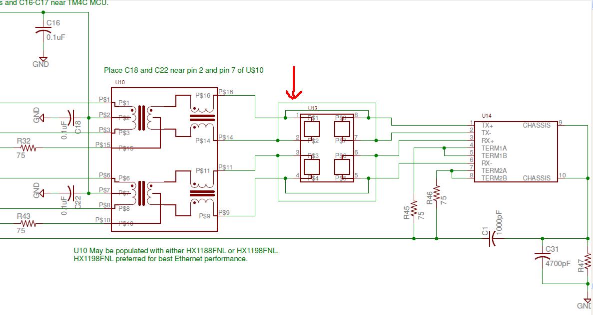
    In TM4C1294XL user guide, Pin1/ 8 ,Pin2/7, Pin 3/6, and Pin4/5 are connected

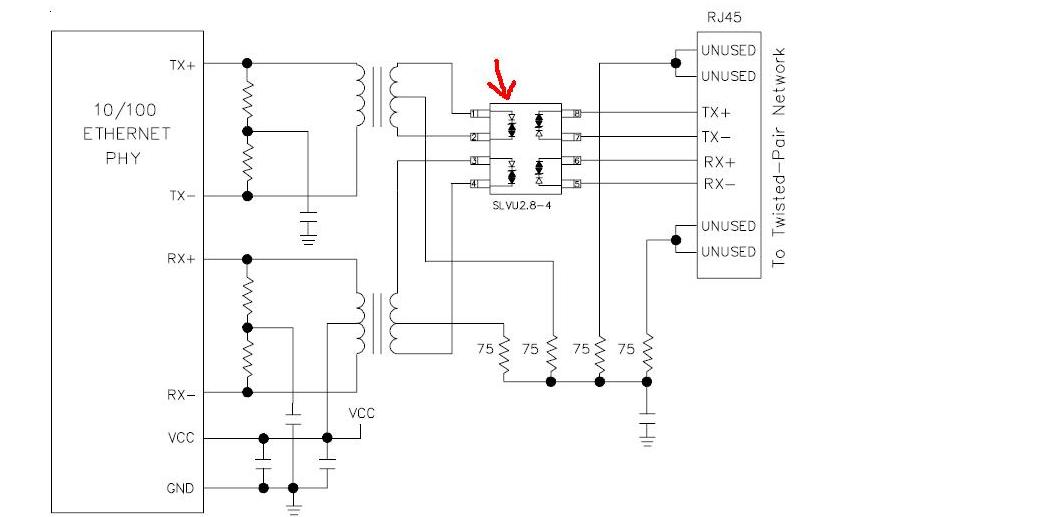
    However, the datasheet(SLVU2.8-4) provided by SEMTECH does not seem like same as the above one.

    The custom board seems to not have the wiring connections in diode array shown on the TM4C user guide.

    Is it not really a matter? both are fine?

    Thanks

    Jin

  • Hello Jin,

    I think that is the issue. The Ethernet pins are getting stopped at the ESD protection.

    Regards
    Amit
  • Hi Amit,

    The wiring configuration of ESD protection was wrong.
    I thank you for helping me out.

    Regards,
    Jin
  • Hello Jin,

    Good to hear that you are now all set and going.

    Regards
    Amit