Hi there,
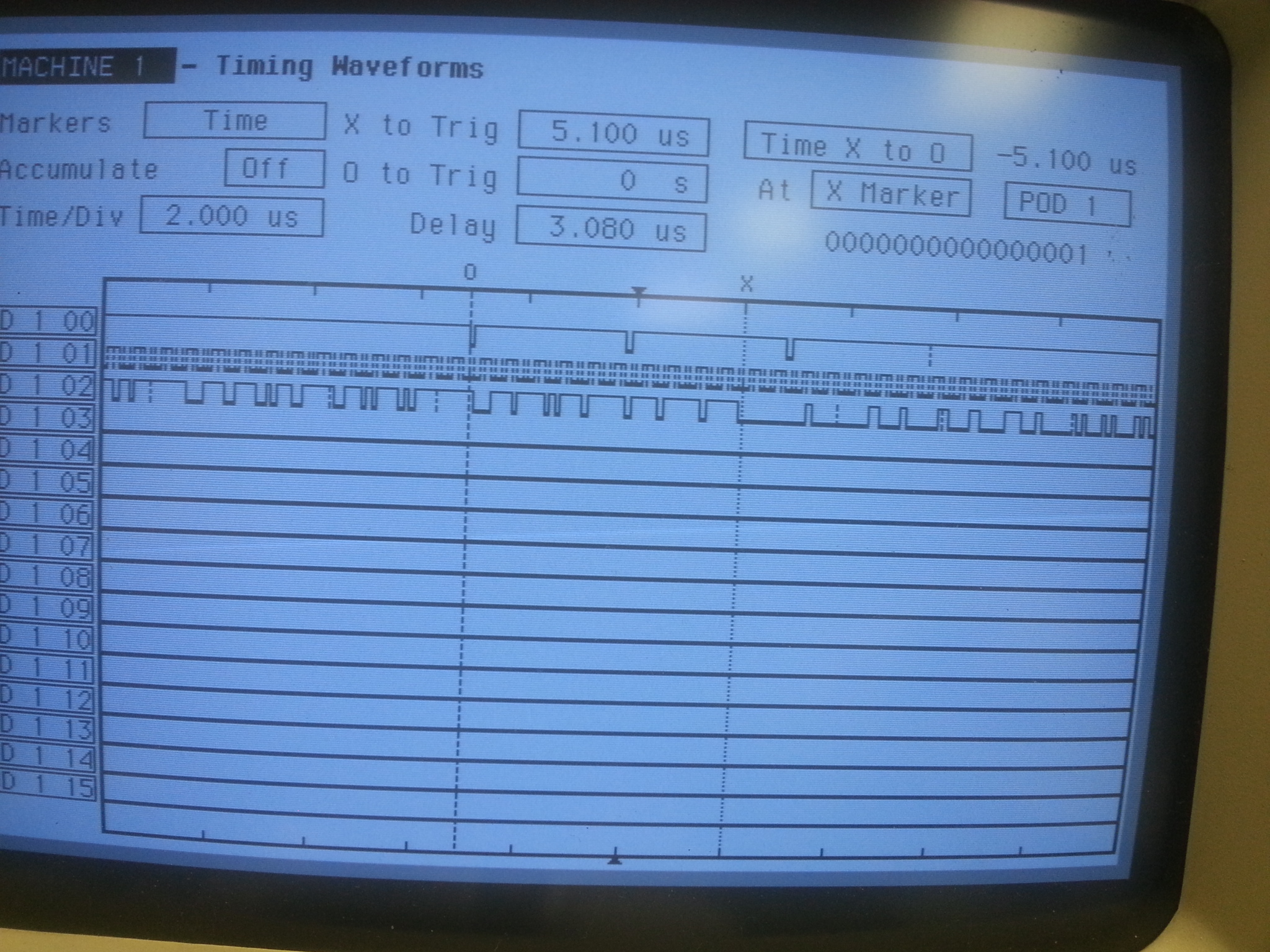
I am using SSI/DMA for the first time and had some questions. I enabled two interrupts, RX/TX, so I expect two, but I saw four instead (No, it will not affect any operation):
Two before the end of the transfer, which is marked by X, two after
Could anyone be so kind to give me some pointers? Thanks!
Here is my SSI configuration:
#include "def.h"
#include "globalvar.h"
#define XFERSIZE 1024
//*****************************************************************************
//
// SSI0 Interrupt Handler
//
//*****************************************************************************
void
SSI0IntHandler(void)
{
uint32_t ui32Status;
uint32_t ui32Mode;
int ui16Idx;
ui32Status = SSIIntStatus(SSI0_BASE, 1);
SSIIntClear(SSI0_BASE, ui32Status);
GPIOPinWrite(GPIO_PORTN_BASE, GPIO_PIN_1, 0);
GPIOPinWrite(GPIO_PORTN_BASE, GPIO_PIN_1, 2);
ui32Mode = uDMAChannelModeGet(UDMA_CHANNEL_SSI0RX | UDMA_PRI_SELECT);
if(ui32Mode == UDMA_MODE_STOP)
{
uDMAChannelTransferSet(UDMA_CHANNEL_SSI0RX | UDMA_PRI_SELECT,
UDMA_MODE_BASIC,
(void *)(SSI0_BASE + SSI_O_DR),
g_ui8SSIRxBuf, XFERSIZE);
uDMAChannelEnable(UDMA_CHANNEL_SSI0RX);
}
if(!uDMAChannelIsEnabled(UDMA_CHANNEL_SSI0TX))
{
uDMAChannelTransferSet(UDMA_CHANNEL_SSI0TX | UDMA_PRI_SELECT,
UDMA_MODE_BASIC, g_ui8SSITxBuf,
(void *)(SSI0_BASE + SSI_O_DR),
XFERSIZE);
uDMAChannelEnable(UDMA_CHANNEL_SSI0TX);
}
}
void ConfigureSSI0(void)
{
uint32_t trashBin[1] = {0};
//
// Enable the SSI0 Peripheral.
//
SysCtlPeripheralEnable(SYSCTL_PERIPH_SSI0);
SysCtlPeripheralSleepEnable(SYSCTL_PERIPH_SSI0);
//
// Configure GPIOA_3 as the SSI Chip Select
//
GPIOPinTypeGPIOOutput(GPIO_PORTA_BASE, GPIO_PIN_3);
GPIOPinWrite(GPIO_PORTA_BASE, GPIO_PIN_3, GPIO_PIN_3);
//
// Configure GPIO Pins for SSI0 mode.
//
GPIOPinConfigure(GPIO_PA2_SSI0CLK);
GPIOPinConfigure(GPIO_PA4_SSI0XDAT0);
GPIOPinConfigure(GPIO_PA5_SSI0XDAT1);
GPIOPinTypeSSI(GPIO_PORTA_BASE, GPIO_PIN_5 | GPIO_PIN_4 | GPIO_PIN_2);
SSIConfigSetExpClk(SSI0_BASE, g_ui32SysClock, SSI_FRF_MOTO_MODE_3,
SSI_MODE_MASTER, 12000000, 8);
SSIEnable(SSI0_BASE);
/* Clear SSI0 RX Buffer */
while (SSIDataGetNonBlocking(SSI0_BASE, &trashBin[0])) {}
}
void InitSPITransfer(void)
{
uint_fast16_t ui16Idx;
//
// Fill the TX buffer with a simple data pattern, and erase RX buffer
//
for(ui16Idx = 0; ui16Idx < SSI_BUFFER_SIZE; ui16Idx++)
{
g_ui8SSITxBuf[ui16Idx] = ui16Idx;
g_ui8SSIRxBuf[ui16Idx] = 0;
}
//
// Enable the uDMA interface for both TX and RX channels.
//
SSIDMAEnable(SSI0_BASE, SSI_DMA_RX | SSI_DMA_TX);
//
// This register write will set the SSI0 to operate in loopback mode. Any
// data sent on the TX output will be received on the RX input.
//
//HWREG(SSI1_BASE + SSI_O_CR1) |= SSI_CR1_LBM;
//****************************************************************************
//uDMA SSI0 RX
//****************************************************************************
//
// Put the attributes in a known state for the uDMA SSI0RX channel. These
// should already be disabled by default.
//
uDMAChannelAttributeDisable(UDMA_CHANNEL_SSI0RX,
UDMA_ATTR_USEBURST | UDMA_ATTR_ALTSELECT |
(UDMA_ATTR_HIGH_PRIORITY |
UDMA_ATTR_REQMASK));
//
// Configure the control parameters for the primary control structure for
// the SSIORX channel.
//
uDMAChannelControlSet(UDMA_CHANNEL_SSI0RX | UDMA_PRI_SELECT,
UDMA_SIZE_8 | UDMA_SRC_INC_NONE | UDMA_DST_INC_8 |
UDMA_ARB_4);
//
// Set up the transfer parameters for the SSI0RX Channel
//
uDMAChannelTransferSet(UDMA_CHANNEL_SSI0RX | UDMA_PRI_SELECT,
UDMA_MODE_BASIC,
(void *)(SSI0_BASE + SSI_O_DR),
g_ui8SSIRxBuf, XFERSIZE);
//****************************************************************************
//uDMA SSI0 TX
//****************************************************************************
//
// Put the attributes in a known state for the uDMA SSI0TX channel. These
// should already be disabled by default.
//
uDMAChannelAttributeDisable(UDMA_CHANNEL_SSI0TX,
UDMA_ATTR_ALTSELECT |
UDMA_ATTR_HIGH_PRIORITY |
UDMA_ATTR_REQMASK);
//
// Set the USEBURST attribute for the uDMA SSI0TX channel. This will
// force the controller to always use a burst when transferring data from
// the TX buffer to the SSI0. This is somewhat more effecient bus usage
// than the default which allows single or burst transfers.
//
uDMAChannelAttributeEnable(UDMA_CHANNEL_SSI0TX, UDMA_ATTR_USEBURST);
//
// Configure the control parameters for the SSI0 TX.
//
uDMAChannelControlSet(UDMA_CHANNEL_SSI0TX | UDMA_PRI_SELECT,
UDMA_SIZE_8 | UDMA_SRC_INC_8 | UDMA_DST_INC_NONE |
UDMA_ARB_4);
//
// Set up the transfer parameters for the uDMA SSI0 TX channel. This will
// configure the transfer source and destination and the transfer size.
// Basic mode is used because the peripheral is making the uDMA transfer
// request. The source is the TX buffer and the destination is theUART0
// data register.
//
uDMAChannelTransferSet(UDMA_CHANNEL_SSI0TX | UDMA_PRI_SELECT,
UDMA_MODE_BASIC, g_ui8SSITxBuf,
(void *)(SSI0_BASE + SSI_O_DR),
XFERSIZE);
//
// Now both the uDMA SSI0 TX and RX channels are primed to start a
// transfer. As soon as the channels are enabled, the peripheral will
// issue a transfer request and the data transfers will begin.
//
uDMAChannelEnable(UDMA_CHANNEL_SSI0RX);
uDMAChannelEnable(UDMA_CHANNEL_SSI0TX);
//
// Enable the SSI0 DMA TX/RX interrupts.
//
SSIIntEnable(SSI0_BASE, SSI_DMATX | SSI_DMARX);
//
// Enable the SSI0 peripheral interrupts.
//
IntEnable(INT_SSI0);
}