This thread has been locked.

If you have a related question, please click the "Ask a related question" button in the top right corner. The newly created question will be automatically linked to this question.

How many independent PWM pins has the Tiva C Launchpad (aka EK-TM4C123GXL)?

Other Parts Discussed in Thread: EK-TM4C123GXL

Hi!

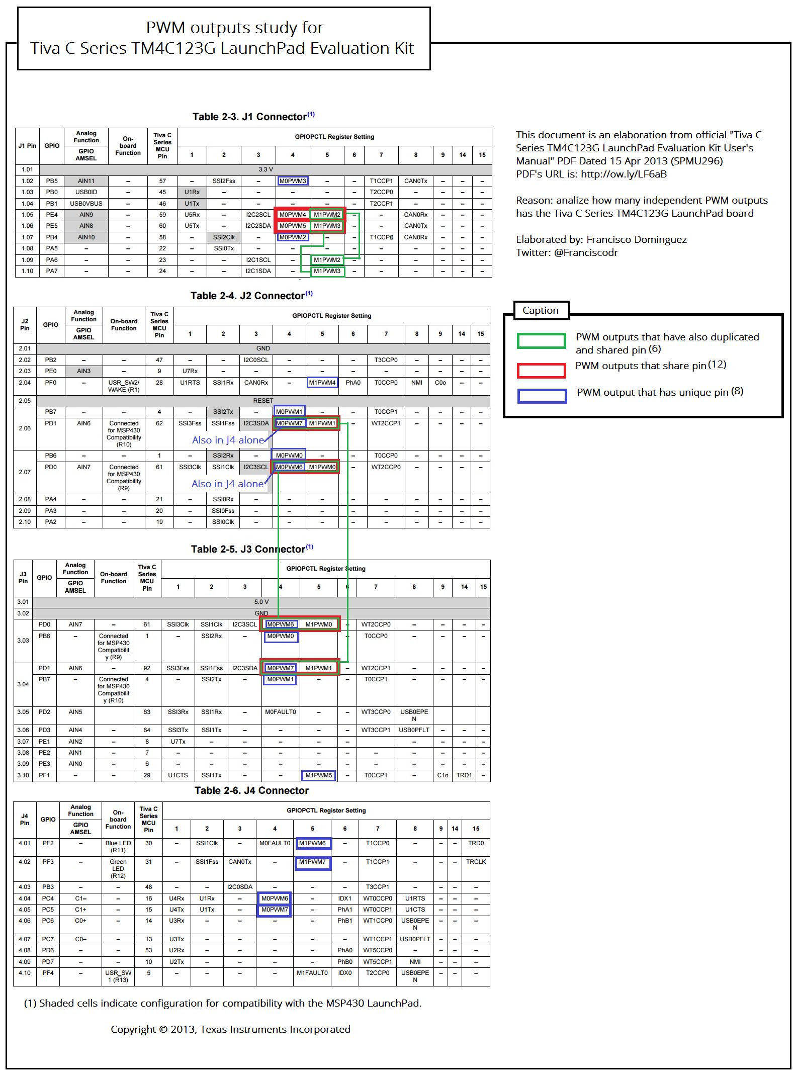
I'm designing a project and I need the 16 PWM outputs that Texas instruments states in the board datasheet Tiva C (EK-TM4C123GXL) board has:

How can I access those 16 PWM outputs in that board? From that board datasheet I see 6 PWM outputs are overlapping in some pins, is that right? If so, in the Launchpad it's possible to use only 10 PWMs...?

Thanks!

  • Hello Francisco,

    All 16 channels are available. The pin showed have two functions of PWM and there are other alternative pins as well.

    Regards
    Amit
  • Hi Amit,

    Thanks for your fast answer. Sorry but I don't see it, could you please tell me which 16 different pins can I use to manage 16 servos by PWM?

    Thanks
    Francisco
  • Hello Francisco,

    Look at the image from your first post.

    1. J1 Connector has M1PWM2 and M1PWM3 are available on PA6 and PA7
    2. J2 and J3 are dual mapping. So if you configure one PWM on J2, other PWM channel can be used for J3.

    Regards
    Amit
  • Hi Amit. Now it is clear. Thanks!

    Kind regards,

    Francisco

  • Francisco Dominguez1 said:
    Now it is clear

    Not to this reporter!    Poster (appears) to seek all 16 PWM outputs from his LPad.    And that - I humbly submit - cannot be done!

    Limiting factor is that PWM_1 only outputs 4 "uncontested" PWM signals - on the LPad.   Indeed - as Amit notes - 2 others may be "massaged out" via the "election" of PWM_1 over PWM_0 - yet that STILL only totals 6 PWM-1 Outputs!     (able to "escape" an unmodified LPad!)

    That's NOT the 16 poster noted.    Limitation (14 PWM outputs) is not w/in the MCU - it is w/in the design/layout of the (launch-limited) LPad pcb.

    Indeed M1PWM6 & M1PWM7 are both "awol" (from all headers) upon this (rather limited) board...

    Excelsior.

  • Hello cb1

    M1PWM6 and M1PWM7 are on J4

    Regards
    Amit
  • Hi Amit,

    I was utilizing the diagram poster presented here.    No J4 was listed.

    Could not imagine he'd miss that.

    Second case (just today) of inadequate postings "spoiling" my time/effort - I'm hi-tailing it from here - unguided posters waste time/effort!   (other, more profitable/fulfilling walls await my head)

    Thanks for your clarification - pity the poster presented incomplete data.   (should I have been surprised?)

  • Hi cb1,

    Thanks for your thoughts. I didn't included at the beginning the J4 as it has not two PWM outputs at the pin.

    I'm trying to understand Tiva C launchpad pinnout PWM outputs. A good way is to prepare a graphical tool. To do so, and thanks to Amit answers I did this now, I hope it helps to clarify it, any helpful comment is welcome:

    Kind regards,

    Francisco

  • Thank you, Francisco. I "take breaks" from harder work - come here - try to be useful. Your diagram showed much effort - I'm no fan of the LPad (econo pad really) and only recently we were gifted w/two - for some unique SWD testing. Thus I "missed" the lacking J4 - my analysis was based entirely upon your diagram.

    If indeed you want (and need) all 16 PWM outputs - you must remove those 2 - 0 Ω resistors (R9,10 I believe).

    Managing 16 PWM outputs may present complications - depending upon your intent/usage. When that many PWM signals are (really) required it may prove faster & simpler to employ multiple MCUs - especially if the SW usage over-challenges.
  • Thank you cb1- (1524606) ,

    Even more from your scarce time.

    Could be great to confirm whether it is needed to remove the resistors you say...

    To keep going documenting I have created a post here.

    Kind regards,

    Francisco

  • cb1- said:
    If indeed you want (and need) all 16 PWM outputs - you must remove those 2 - 0 Ω resistors (R9,10 I believe).


    I hate those resistors, never found them useful at all.


    Hi Francisco,

    Just asking, you do know the timers offer a basic PWM signal, right? Though they lack functions that the PWM module offers (and maybe not as precise, never compared side by side).

  • Francisco Dominguez1 said:
    great to confirm whether it is needed to remove the resistors you say...

    Those 2 -  0Ω R's - tie 2 pairs of MCU pins together - do they not?   And - as fate has it - don't you require unique use of those very pins - to harvest all 16 PWM outputs?

    Your responsible for reviewing the schematic - making that confirmation - "helpers" here can (only) signal the alert.

    Rapidly advancing poster Luis notes his "hatred" for those 0Ω "roadblocks."    Suspect he's got good reason...   (but leave to you to confirm...)

  • Thanks !

    Yes I checked pins and schematics and I need to remove both R9 and R10, as they connect PD0 with PB6 and PD1 with PB7. Some people describe it here.

    Why is the board like this? Just, as it's stated in the datasheet, to have compatibility with the MSP430.

  • Vendors - even large ones - do not always make, "best/brightest" decisions.

    Despite countless "crash/burn" of users (some experienced & skilled) vendor allows those resistors to remain.

    This reporter has long suggested that those (helpful) resistors be packed & marked in separate bag - to be added by those (few) who seek such "compatibility."  Vendor refuses (or moves like, "herd of turtles") thus the vast majority suffer - so that a "few" (may) be aided...

  • Hello cb1

    Thanks, we do not always. Mounting the resistor is not feasible for some folks though. However it should have been a header instead of resistor.

    Regards
    Amit
  • Hi Amit,

    While mounting these 2 smt resistors (may) not be feasible for some folks - would it be simpler/faster for those same (mount challenged) folks to change their (damaged) MCU?    ( i.e. remove ,  buy new one and then "mount" a QFP MCU?)  

    Dreaded, "output to output" MCU contention has long plagued many -  including well-experienced, guru poster Roberto.

    As "far and away" most do not require such (past) compatibility - and the potential for (serious) damage exists - allowing those 0Ω "destroyers" to continue their (unwanted) pcb residency - makes little sense...