This thread has been locked.

If you have a related question, please click the "Ask a related question" button in the top right corner. The newly created question will be automatically linked to this question.

Tiva C Series TM4C129xNCPDT MCUs the allowence of maxiumum speed of the GPIOs

Other Parts Discussed in Thread: SN65HVS880

Hello everybody.

I wonder the maxiumum speed of the GPIOs of the Tiva C Series TM4C129xNCPDT MCUs.

I would think of using the sn65hvs880 Digital Input Serializer.

So that, i need to know the working speed of the GPIOs. GPIOs speed should be calculated according to 120MHz running issue. I have not found any information on the dedicated data sheets.

Another wish to tell you all, that is the peripherals clock speed and their running procedure. What is the conversion time of ADCs?

  • Hello Zextro,

    The peripherals are clocked with System Clock. However some peripherals have dividers which limit the frequency on the interface e.g SSI, UART, I2C while others like GPIO are dependent on the how fast the CPU or DMA access is. So if CPU access a GPIO Pin once every 10 cycles the GPIO rate of access will be 1/10th of the system clock. The CPU does have limitation as it would be requiring to access Instruction to perform GPIO access so getting 120MHz toggle rate at an IO may not be possible.

    Regards
    Amit
  • Amit Ashara said:
    getting 120MHz toggle rate at an IO may not be possible.

    Might a stronger, more direct statement read, "120MHz toggle of a GPIO (even a fast one) w/system clock of that rate - is impossible!"

    Perhaps best, "Not to give poster such hope..."

    As poster seeks, "high speed operation" - both GPIO & ADC - perhaps a more advanced MCU should be targeted...

  • Hello cb1

    Indeed. 120MHz IO Toggle Rate cannot be achieved as back to back data access will reduce it by 1/2 and this is true for timers as well where a count of 0-1-0 would also half the IO toggle rate.

    Thanks and Regards
    Amit
  • Hi Amit,

    That's a great follow-up - and indeed such holds true across all ARM MCUs (all makers) this class MCU.

    Poster must realize that your suggestion here of Timer output - (likely in PWM Mode) yields the highest possible frequency output - as the Timer's toggle rate is "not" subject to delays imposed by code loops.

  • That's an interesting little device. I hadn't seen that particular one before. Thanks

    Any reason you wouldn't use the SPI peripheral to interface with it? It's a lot faster than bitbanging an SPI interface. Also note that the maximum data rate is specified at 1Mbps, although the maximum clock rate is specified at 20MHz. A curious contradiction or something I didn't pick up on in the data sheet as to the difference. Maybe they mean that with debounce filtering turned off you can conceivably read a signal changing at 1MHz but it's far from clear to me. The IC certainly does not appear to be meant for rapidly changing inputs.

    Does the '129 not support SPI?

    Robert
  • Hello Robert

    TM4C129 does support SPI.

    Regards
    Amit
  • Never - from anyone's read of poster's request - would use of (the most appropriate) SPI have dawned! He spoke entirely to GPIO - how do you "miss" SPI?
  • Hi Amit Ashara,


    Thank you first of all for your quick reply.


    I asked that question to execute serial data input to mcu over sn65hvs880 device. As you know, that device works mostly (I/O max rate) 1000kbps. Hence, i needed to know how quick work the GPIOs of the dedicated MCU. Because i need to add wait-state between high&low transition side of the data&clock of the sn65hvs880 in order to execute the data transfer.


    you told me " So if CPU access a GPIO Pin once every 10 cycles the GPIO rate of access will be 1/10th of the system clock. "


    If i got correctly, it meant, 1/10th of the system clock (0.1*120Mhz = 12Mhz) high side and vice versa.

    Can i write to bit-field (1 or 0) of GPIOs register in order to make the output “high " of GPIO then do the same to others (GPIOs) back to back? Or Do i have to wait some cycles to write others?


    I used that above device before with F28069 C2000 MCU. I got some interesting GPIOs performance from Piccolo. Even it has been written on the data sheet of the C2000 device, that is, between the transition period of the GPIOs (it means from high to low or vice versa), the called MCU should wait at least 5 CPU clock cycle to operate assigned assertion if i choose to use GPxDAT registers of the GPIO. It means, F28069 Piccolo device never gives an affirmative result if i try to change the PIN's working state within 5 CPU clock cycle. However, TI solves this problem with SET-RESET register option. Let me explain you with some pseudo code at below.


    for C2000 Piccolo F28069;

    GPIO1 = output
    GPIO2 = output

    GpioDataRegs.GPADAT.bit.GPIO1 = 1;
    GpioDataRegs.GPADAT.bit.GPIO2 = 1;

    if i write pseudo code like above, the first GPIO1 never works because of not to wait at least 5 clock-cycle.


    GpioDataRegs.GPADAT.bit.GPIO1 = 1;

    asm("nop");    asm("nop");    asm("nop");    asm("nop");    asm("nop");
    GpioDataRegs.GPADAT.bit.GPIO2 = 1 ;


    If I write like that, there is no problem. It works.


    For now, let me ask you.


    When I use TM4C129xNCPDT MCU, Should I wait some cycle between 2 GPIO operations? For example


    GPIOPinWrite(GPIO_PORTA_BASE, GPIO_PIN_0);

    ( Should I wait some cycle or not?)

    GPIOPinWrite(GPIO_PORTB_BASE, GPIO_PIN_1);


    But I can infer from your explanation, I guess, I should wait some cycle between 2 GPIO’s operations. İf the GPIO peripheral works as 1/10th clock cycle of the system clock source.


    GPIOPinWrite(GPIO_PORTA_BASE, GPIO_PIN_0);

    NOP;   NOP;   NOP;   NOP;   NOP;   NOP;   NOP;   NOP;   NOP;   NOP;    (10x NOP)

    GPIOPinWrite(GPIO_PORTB_BASE, GPIO_PIN_1);


    Are all these correct to mention about them ?

  • Hello Zextro.

    Simply put, the following sets of write will work and there is no need to put any delay statement.

    GPIOPinWrite(GPIO_PORTA_BASE, GPIO_PIN_0, GPIO_PIN_0);
    GPIOPinWrite(GPIO_PORTA_BASE, GPIO_PIN_1, GPIO_PIN_1);

    When I mentioned 1/10th it means that when the first statement is executed and there is a NOP or some other action like an interrupt, the Back to back write of the pin shall be dependent on the same. If none then the fastest the two statements shall execute is the fastest GPIO toggle. Note that TM4C12x is not limited as Piccolo is.

    Regards
    Amit
  • ZextroM said:
    I wonder the maxiumum speed of the GPIOs of the Tiva C Series

    May I note the apparent conflict in poster's (real) needs/desires?    Quote above - from his 1st sentence - opening post.

    His latest post (earlier today) seeks to (deliberately) burden & slow the MCU!    Which is it - what is Amit to advise?    How soon will that change?

    Posters need to fully/properly (decide upon) some goal when posting - and then maintain (some) consistency.

  • ZextroM said:
    I asked that question to execute serial data input to mcu over sn65hvs880 device. As you know, that device works mostly (I/O max rate) 1000kbps. Hence, i needed to know how quick work the GPIOs of the dedicated MCU. Because i need to add wait-state between high&low transition side of the data&clock of the sn65hvs880 in order to execute the data transfer.

    Why on earth are you not using SPI for this??? It would solve all your timing issues(1) with no need to create pseudo assembly code.

    Robert

    1 - which I strongly suspect you have mis-interpreted but that's a separate issue.

  • I know what i should use ... this issue should also be known by user to do something by having knowledge ... I have also used so far 3 SPI unit, I wanna put that last unit as reserved ... Is ıt completely clear why i wanna choose that option ? SN65HVs880 is also fully suitable for PLC inputs that is used directly for 24V applications
  • ZextroM said:
    I have also used so far 3 SPI unit, I wanna put that last unit as reserved

    You do realize you can use an SPI unit for more than a single device (even w/o daisy chaining)? I can envision you running into resource issues on the SPI if you have a dozen or two devices on each or you are running continuous streams of data on them at high data rates but those cases also would make bit banging difficult since your processor would be heavily loaded handling the data.

    Timing by delay loops is hazardous at the best of times. The best case being using assembler and no interrupts or multi-tasking.

    ZextroM said:
    Is ıt completely clear why i wanna choose that option ?

    No, it seems a lot of effort for no reason.

    ZextroM said:
    SN65HVs880 is also fully suitable for PLC inputs that is used directly for 24V applications

    That seems a bit of a non-sequiter.

    Robert

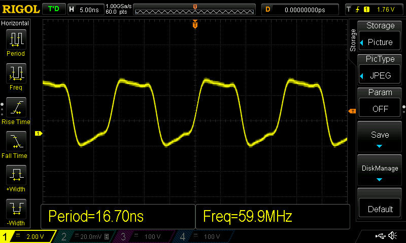
  • Since I had a 129 launchpad handy, I decided to see how fast an I/O will toggle. Here you go...

  • Might you describe how you configured the MCU to achieve this?

    Suspect this resulted from a Timer set to PWM mode at highest frequency - better if you'd describe. Thanks this effort.
  • My intent was to answer the OPs question without clouding the issue with a lot of technical detail. ;-)

    You are correct, this is done with a timer in PWM mode. Doesn't help much for serial communication.

    Randy

  • Thank you - appreciated.

    One wonders if that waveform could be improved via an increase in output current setting - or if that capability exists - when the MCU pin is configured as a Timer? So many vendors producing ARM MCUs - hard to keep straight - which MCU does what?...
  • The port pin is configured to use 12mA of current. The waveform distortion is due to the board layout.
    Randy
  • Looks like you've given the pin, "every chance." The "excess" rise-time (not so evident @ the fall) gives me pause to agree that this is solely "layout."
  • The rise and fall take place over a period of only two samples (it's sampling at a GHz and by eye the rise/fall is ~2nS). It would be more obvious with the interpolation turned off, one of the perils of DSOs.

    Randy, if you know, What's the 'scopes bandwidth at that time scale?

    You also do not need much inductance or capacitance at that edge frequency to give you a 2nS edge.

    Robert
  • The scope's bandwidth is around 130 to 140 MHz.
    This was measured on the header "X11", pins 4 and 6 on a "Connected Launchpad" and the traces go all over the place to get there.

    Randy
  • Thanks Randy, so around 10nS. The edge rates exceed the 'scopes bandwidth and are sufficient to provide the rise/fall times displayed. The layout probably doesn't help but I don't think you can be assured you are seeing the true edge response here.

    You may also need a good probe setup as well to get a better view.

    I wouldn't read anything into the rise/fall either.

    Robert
  • Understanding how to interpret your instruments and their limitations is all part of the game.
    I get that.
    The purpose of my post was to demonstrate that the port pin will toggle at 60MHz., nothing more.
    I have other scopes and probes here on the bench that can do a better job of representing the signal.
    The Rigol is an easy way to publish a screen shot.

    Randy
  • Believe that I speak for many here when we acknowledge your work and thank you.

    Perhaps - as an add-on assignment w/more "real world" value - an examination may be made to determine which MCU peripheral resource and method enables the "fastest" clocking of one - or multiple bit data - between the MCU and an external device.    The maximum pin toggle rate - demonstrated here earlier - is not capable of carrying any sync'ed data payload.
     
    SPI appears to lead the "speed" pack for single bit data exchange - 8 or 4 bit parallel exchange (outside of the EPI) appears a greater (& slowed) challenge...

  • cb1- said:
    Believe that I speak for many here when we acknowledge your work and thank you.

    Absolutely.

    And Randy, no intent to lecture in my post.  Just figuring out what the limiting factors are.

    Robert

  • Not a problem.
    Looks like this thread has been knocked way out of orbit.
    If anyone wants to pursue parallel peripheral interfaces on another thread, I'm game.
    I have done several designs that use a bit banged16-bit external memory type interface to an FPGA. just have to give up the ports.

    Randy
  • Randy Ott said:
    Looks like this thread has been knocked way out of orbit.

    And - that may "not" be such a bad thing!