This thread has been locked.

If you have a related question, please click the "Ask a related question" button in the top right corner. The newly created question will be automatically linked to this question.

Tiva™ C Series TM4C1294 Connected LaunchPad - Which chip UARTs are most easily avail?

I have the Launchpad connected on the Debug ICDI with VCP using UART0.

I would like to use other UARTs discretely on the Booster pack headers but its confusing to me to see which UARTs are easiest to be used. I want to be able to use UART0 with additional UARTs. (At least one additional UART, preferably more)

I basically have 2 questions, one sw one hw:

1. My sw question:

I am looking at replicating the uart_echo sample for a different UART. Eventually I want to pass data between multiple UARTs using uDMA channels. The code currently uses UART_BASE0 to select the UART. But I dont understand why only UART0, UART1 and UART2 are defined as possible UARTs in uartstdio.c:


//*****************************************************************************
//
// The list of possible base addresses for the console UART.
//
//*****************************************************************************
static const uint32_t g_ui32UARTBase[3] =
{
    UART0_BASE, UART1_BASE, UART2_BASE
};

Could uartstdio.c be expanded beyond UART2 or is there a hardware reason why only UART0,UART1 and UART2 are used in this mode?

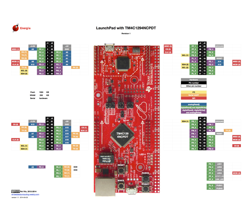
2. My hw launchpad question: Which UARTs beyond UART0 are easiest to set up given the hardware connections?

I looked to use UART1 or UART2 given my possible restriction listed in question #1 above.

When I look at UART1 cannot find U1Rx or U1Tx in the boosterpack tables (But curiously I see other signals from UART1 brought out to the headers).

I do see UART2, U2Rx and U2Tx in 2 spots between boosterpack and breadboard connections:

A. Header pins A2-6, A2-7(GPIO PD4, PD5) This seems to be mixed up the CAN bus and JP4 and JP5. It seems that I would need to move IDCI from UART0 to UART4? I prefer to stay on UART0 until #1 is resolved.

B. Breadboard adapter pins 25, 27 (GPIO PA6, PA7). If I could manage to solder onto these pins, I'm concerned about the schematic note:

PA6 and PA7 are also used by the onboard radio.
Configure the radio to tri-state these GPIO before
using them on the boosterpack interface.

I see no mention of Radio elsewhere except in actual BoosterPacks. Is this a typo or how would I "Configure the radio to tri-state'?

Thanks for any help,

-Phil B

  • Hi Phil,

    Sincerely I can't tell you why the other UART modules aren't on the util library, but you could always use the driver library or adapt the util library. could you give some clarification?

    To check which pins allow UART just look bellow the board for the pin names and check the datasheet on the UART section which ones are for the UART.
    More easily check this image bellow. It shows in orange the UART pins with the UART module number between curved brackets () <-- those ones.


    If you want to use any UART to communicate to the PC you always need a Serial to USB converter (the ICDI takes care of that for the UART0 and UART4 only). Any other UART module you require a extra Serial to USB converter or disconnect one of the UART/CAN set of jumpers and connect your desired UART pins to the ICDI side of the removed jumpers.
    Now how the ICDI handles receiving the UART0 and UART4 signals I am not sure. My guess is: You shouldn't use them at the same time with the ICDI (if you still need them both you should disconect one of the set of jumpers).
    I've never seen that reference about the radio, weird. I used all 8 UARTs simultaneous without any problem, weird because I had no problems with UART4, it didn't send anything to the ICDI


  • Hello Luis, Phil,

    1. The software can be modified for adding additional UART's other than UART0-2 and I will a request for addition in the software

    2. The bread board connector X11 has almost all the signals (Section 2.1.6.3 of the Tiva™ C Series TM4C1294 Connected
    LaunchPad Evaluation Kit User Guide)

    Regards
    Amit
  • Thanks Amit and Luis,

    Yes I will be using a USB to serial outside of the IDCI chip. I want my testing to be closer to my actual application hence the access to UARTs aside from the IDCI. I will try to get the breadboard connector soldered in to have access to all the UARTs.

    Thanks Luis for the feedback that all 8 are working for you!

    And I will locally modify the sw to use all ports. Thanks for the help!

    -Phil