This thread has been locked.

If you have a related question, please click the "Ask a related question" button in the top right corner. The newly created question will be automatically linked to this question.

Easy Electrical Question - Before I fry this board.

Other Parts Discussed in Thread: SN65HVS880

Hi All:

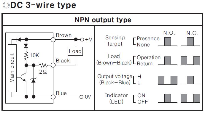
I have a Tiva TM4C123G LaunchPad and want to connect it to a Proximity sensor.

When the Proximity circuit is closed, I'm seeing that the "output" is 3.27v and 2.00amps (yes, amps).  

I'm worried that when I connect the Sensor to the PIN that I will fry the board.

I'm typically used to working with components at the 20ma level and my understanding of the electrical portion of this is a beginners level at best.

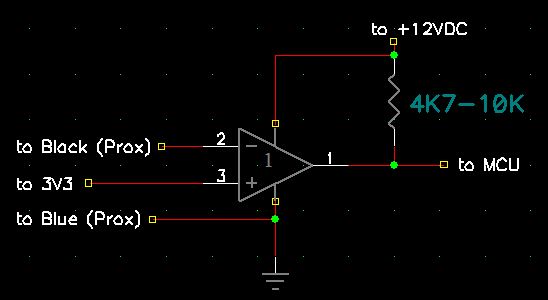
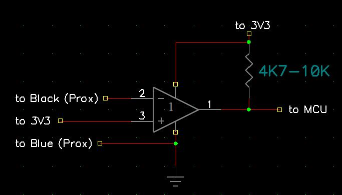
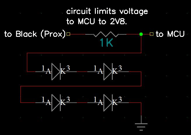
Will I fry the board if I hook the sensor up to it?  Do I need to add a Resistor to this circuit?  

Any help would be greatly appreciated.

Thanks

Rick

  • Hi Rick,

    What sort of proximity sensor do you have? :o

    That seems like a straight short circuit. If you feed 2A to your pins, yes you will fry them and probably do a lot of damage to the rest of the MCU.
    Without knowing which sensor you have it's hard to help you (proximity could be a ton of things).

    Edit:
    For future reference on the MCU proper operating conditions can be seen in your part datasheet under 24.3 Recommended Operating Conditions. There are other tables for absolute maximum, the absolute maximum values although should not damage instantly your MCU, they will degrade it quickly and should be avoided, instead you should respect the limits imposed in chapter 24.3 on the datasheet.
    For the GPIO Table 24-6. should give you the info about the maximum input voltage.
    Although I didn't find anything about maximum input current, you should not force much current, anything like 1mA is already plenty enough for most cases (high speed readings would need to consider input capacitance and impedance).

  • If you are to connect the sensors output to an input on the TIVA, then the current draw will only depend on the TIVA's input impedence, so no problem(as long the voltage does not exceed the TIVA limits).

    Now if the(this) sensors output draws 2 amps, then something else must be(is currently) connected to it...

  • Suspect you'd fare better by providing a link to your sensor - thus enabling those here to "better" understand & contribute...

    Your reported "seeing" of 3V27 @ 2.0 amp "output" begs (some) description of "how" you made such observation.   I'd place tall stack of chips against those numbers being the "real/proper" output rating...

    As always - when client, boss, teacher or (poster) here describes something as, "easy" alarms sound & iron (or plastic) dome deploys...

  • Or, he has already something connected on the output(as I mentioned above), or worse, he just short circuited the output with his amp meter...
  • Capabilities of the device aside, connecting it directly to the microprocessor pins is probably "a BAD idea".

  • It probably is 'a bad idea', to connect it directly, but it shouldn't harm the input either, as long the voltage is between the limit's.

    The TIVA input will never draw more current than it needs, the worst case what will happen is that the sensors output will not switch if the impedance is to high.

  • Minus the (long requested spec) all here remains "guesswork!"
  • Keep in mind that most prox switches are industrial devices designed to operate at 24V.

    Even if not a 24V device I would never connect an external device directly to a micros input, it doesn't take much to destroy a modern micro.

    As cb1 says at this point it's all speculation

    Robert
  • marc_rir, cb1-, Robert Adsett:

    Everyone, I was pretty blown away at the swiftness, quantity and qualities of the replies. Thank you.
    I do volunteer work on Sunday nights, I rattled off the post and walked out the door.
    I was pretty bummed out not to be able to immediately reply to your posts. Thanks for your patience.

    The Proximity is a PR30-15DN proximity sensor used in an NPN configuration.
    www.farnell.com/.../1599273.pdf
    Look on page D-23 for the Part #.

    I'm using an old PC Power supply, feeding the sensor with the 12V wires.
    To go from 12V to 3V (off of the sensor), I'm using a Keedox® DC/DC Converter 12V Step Down to 3.3V 3A Power Supply Module, Non-isolated.

    As I read the specs on the Converter, I can clearly see where this thing will output 3A.
    Wonder if my I2C chips are fried now.... :-)

    That's the setup. Electrically, it "works", in that I can see 3V 2A when near metal and nothing when on paper.
    I was hoping to use a pin on the Tiva to detect closed/open circuit.

    I'm using 12V because I want to eventually run some motors off of this circuit.
    I completely missed the Amp issue until the very end when I could not get a simple LED running when there was a closed circuit.

    I am sure there are TONS of things to talk about here.
    For instance, how do I go from 12V to 3V and only allow 50ma-100ma for instance?
    Am I worried about a current drain/spike when the motors turn on/off. Yes. Have I figured it out? No.
    Programatically, I have I2C, UART, ADC, GPIOIntEnable and other fun things running; but, the electronics is brand new to me.

    Your answers have been most helpful in that it sounds like what I am doing is not... ummm... "optimal".
    If you have anything that you think would be helpful, pass it on. This has been a great learning experience.

    Thank you.

    Rick
  • Thank you - appreciated - my suggestions follow:    (for clarity I present the key drawing - your device)

    I've tried now three times to add verbage to the above drawing - "Post" button spins & spins - never completes.   I've had to copy/past to salvage that writing - it appears next post....

  • Key to that drawing is the presence of the NPN transistor - which when switched on - and if the current through that transistor is w/in spec - will cause the Blue (0V) and Black (switched terminal) to come (nearly) to the same voltage potential. (less the drop thru that 2O resistor - imposed between the NPN's collector and the black terminal)

    That's "classic" NPN transistor use & application - so long as current (and voltage) are w/in the transistor's capability - all should be well. Note the "overlap" of the right-most signal graph - when your sensed target is present the "load voltage" (between brown-black) is greatest while the "output voltage" (between black-blue) is at minimum. Note too that the Led indicator is ON during that "overlap" condition - just described. (that's for the N.O. contacts)

    Now I don't believe that we (yet) have sufficient info to know the purpose nor utilization of your MCU. This proximity sensor - by itself - is quite capable of switching on/off a (proper) load - and indicating that upon its own Led. It is the presence of the target which causes this (desired) switching action - no MCU activity is required - at least that's unknown - at this stage.

    Should you wish to "monitor" the state of this prox switch w/your MCU - a (reasonably safe & simple means may be via the imposition of a voltage comparator - between the black wire/terminal and your MCU's selected input pin. I'd power that comparator from 3V3 - with a 10K pull up resistor at the comparator's output - which will make the signal levels "safe" for your MCU. The comparator may be wired to output either a "logic high (3V3) or logic low (near ground) based upon the voltage the comparator "sees" between "blue-black."

    If helpful I'll supply a schematic - its nearing 20:00 in US Midwest & I'm done - this day...

    Perhaps I've missed - but 2 (quick) scans of the 5-6 pg. data did not reveal the max current which that NPN could safely control. When you add a motor - it would connect between brown & black - and the motor would be "off" until that NPN "turned on" which causes black to drive "close" to ground potential. That NPN must be able to support that current - w/out overheating - and at all of the temperatures your system may encounter...
  • Here's a schematic - there are many ways to achieve your goal - this is just one.    Its merit is safety for your MCU - only 3V3 or ground will be presented to your MCU.   Comparators are available in many forms (some in duals/quads) this is just one example...   Note that the Prox ground - your 12V power supply ground and 3V3 ground all must be made common (tied together).   Only 3V3 powers the comparator - thus it should buffer/protect your MCU.

    In this implementation - when your Prox "turns on" (senses target) the black-blue voltage should approach ground - which causes the comparator's output to turn on - and provide 3V3 into your MCU.   (and that's current limited by the pull up resistor (shown).   When the target is "out of range/removed" the blue-black voltage should exceed 3V3 - and the comparator's output voltage will approach ground...

    Note: I've edited to change comparator's power to ~12V (to exceed any voltage applied to either input pin).    Such comparator - to protect the MCU should employ "Open Collector Outputs" so that the output voltage fed to the MCU is limited to the 3V3 (as shown) provided by the output's pull-up resistor.

  • A couple of notes to add.


    First, PC power supplies often require a minimum load to maintain regulation.
    Second, if you measured that 3A current then the power supply may have been the limiting factor not the prox switch. That may have saved you the prox switch if that is the case.
    Third your biggest danger of damaging the circuit is actually voltage. It is only after voltage has caused ddamage that the current capability will finish the job.

    The comparator is good but a number of comparators will not withstand 12v on an input pin when supplied from 3V3. I wonder if a small relay with a 12V coil might be a better choice. Wire the relay coil as the load and the tips switch 3V3 inputs. If you want the prox to switch the motor as well a second relay wired in parallel would do that. Needs coil suppression but it is iinherently isolated. It may also be a better match to your ccurrent skill set. The comparator or an opto isolator might be a better volume choice but a relay is easier to wire.


    Robert
  • Robert Adsett72 said:
    The comparator is good but a number of comparators will not withstand 12v on an input pin when supplied from 3V3.

    You are (again) indeed, "Correct Sir."    Such was my screw-up during last night's rush.   To resolve I've edited the schematic to show the comparator powered from 12V (or the same voltage fed to the "top" prox. pin.)    To best protect the MCU I've specified an "open collector, output" style comparator - which greatly facilitates output voltage selection.   (the pull-up shown returns to 3V3 - perfectly mating to the MCU)

    Driving to work this morn I realized that either a low voltage zener diode (< 3V3) - or a series connection of several silicon diodes - either connected to that black prox lead or terminal - likely eliminates the need for the comparator.   Zener may prove risky - as most zeners do not exhibit a sharp voltage "knee" when the zener voltage is below 4V.   Four series connected silicon diodes w/current limiting resistor should protect the MCU while enabling adequate signal swing @ the MCU.

  • There is a resistor pull-up scheme that's probably a little more robust. Treat the prox as a switch rather than a voltage source.

    Also the sn65hvs880 about which there have been questions recently would work. If I get a moment I'll try to sketch out the relay and pull-up approaches for completeness purposes.

    Robert
  • Robert Adsett said:
    There is a resistor pull-up scheme that's probably a little more robust.

    Now we disagree!    Return your gaze to the drawing I cut/pasted/presented - you'll note that a 10K R (rather admirably) serves that "pull-up" purpose!    And its already there!    (w/in the prox switch)

    That 10K R w/in the prox forces my series R to be much higher in value to enable the signal to exceed the combined "drop" of those cascaded diodes.   (schematic already amended...)   [edit: this poster pleads, "temporary insanity" for prior sentence.    So long as that prox 10K remains "pulled up" to ~12V - the resistor in my schematic is not truly needed.     Series diodes will "see" ~2V8 until the NPN turns on - which reduces that diode voltage to near zero - thus complying w/MCU's desired logic level, "signal swing."]

  • I did say more robust, not that it didn't work.

    Provided the insert worked.  Here is a simplification of what I have used in the past

    R1 forms the pullup to 12V sized to be noise resistant (by providing a good strong current flow) and provide sufficient operating current.

    R1, R2, and R3 for a divider chain to reduce the voltage to the range of the micro's high input.

    C1 provides noise filtering and a little surge capacity

    D1  Provides power to the Prox while guarding against high voltage connections

    D2 (Optionally) provides protection against shorts to positive supply. When the Prox pulls this low there will be 1V5 to 2V between R1 and R2, The R2/R3 divider will reduce this to be under the micro's low voltage threshold

    R2,R3,D3,C1 provide protection against pulses (and if D1 is not present high voltage connections).

    C2 is optional but will provide wetting current  and some filtering if present

    D4,R4 provides a 'ground' connection with protection against connection to a negative source with R4 protecting against shorts to positive.

    Not shown are protection against shorts on the power feed and EMC protection.

    An option Schmidt trigger inverter is shown that would precondition the input before it reaches the micro.  Also would act as a last ditch sacrificial lamb to protect the micro.

    This will also work with switch inputs and two wire prox switches.

    Robert

    That took multiple tries but it looks like the image is finally there.

  • OK an ugly drawing of the relay version.  I will try to clean it up later

    I think this is simpler the understand. 

    D1 provides polarity protection,

    D3 (diode) and D2 (zener diode) provide coil suppression.

    R1 is a pullup to the micro's power supply.

    As before a Schmidt Inverter can be used to clean up the signal.

    One of the advantages of this configuration is that the coil effectively isolates the micro from off board influences. The relay could be replaced by an optocoupler fairly obviously.

    Again this will also work with switches and two wire proxes

    Robert

  • Note: your 2nd diagrammed post "crossed w/this response."   This writing references your 1st diagram & definitions.

    Believe that you've provided a very complete, "MCU input level shifting & protection circuit" for this community - good job & thanks.    And - your use of that (potentially) "sacrificial" input gate/inverter makes tremendous sense.     (may save the repair/replacement of a 64 pin (or larger) MCU - do that once - sure to be (one hopes) your last!)

    Good and robust as your circuit is - should not we "adjust" our design to the expressed "needs/wants" of the client?    And - thus far - poster (while expressing appreciation) has yet to demonstrate his requirement for so, "bullet-proof" a circuit.   My effort was "quick/dirty" and, "Good for (most) G'ovt Work!"   Over design may not always prove best - and as the number of components increases - the robustness/reliability (usually) degrades.

    Poster did (ever so briefly) mention his desire to, "Run a motor" in this exercise.   And based upon the current demand of that motor - and the safe rating of the prox's NPN switch transistor - the size/selection of your "R4" (which is situated directly in the ground path of prox) may have to be carefully calculated & considered.    Minus that mention - and user awareness - robustness is likely to be sacrificed...

    Tradeoffs - and "devil in the details" - all conspire to demand full/adequate communication between the user & solution provider...

    May I note that poster (once again) titled this as, "Easy Electrical Question!"    (easy {perhaps} when all facts are known, organized & presented {in detail} w/clear budgetary, size, usage and delivery guidelines!)    Is this (still) easy? 

  • cb1- said:
    Note: your 2nd diagrammed post "crossed w/this response."   This writing references your 1st diagram & definitions.

    cb1- said:
    Poster did (ever so briefly) mention his desire to, "Run a motor" in this exercise.   And based upon the current demand of that motor

    That's the second reason for the relay version. You can easily run two relays in parallel on the single prox detector.  The second relay can run the motor.  This has the advantage of being able to run and test either the motor or logic circuit separately and more important removing the motor noise from the board (except as it is introduced through a common power supply).  It would also allow running the motor on a separate power supply further reducing noise problems.

    The first reason for the relay version is I think it is easier to understand and build.

    You're right about the simplicity of the first version.  I don't know about you but I usually see more mistakes in Q&D lashups then one built with a minimal amount of protection.  I still do them though. I do think it's worthwhile letting know there's more to building a reliable input than just wiring it naked to the micro. A hobbyist might not need to provide full EMC protection but protection against inadvertent miswiring might be even more important.

    Robert

  • cb1- said:
    Is this (still) easy?

    Isn't that one of the rules?  "It's never easy"

    ;)

    Robert

  • Truth in advertising - I never even considered a relay - or two - with a 2nd power supply to (greatly) reduce noise & related issues. (almost always a nightmare - best prevented rather than "cured.")

    As for "quick/dirty" our small firm requires "2nd set of eyes" and written description - so that a signed/dated, "paper trail" exists. (proves so helpful - days/weeks downstream when we wonder - wtf?)

    One of our methods in "preventing harm" from such Q&D efforts is the design/development (and strict use) of multiple, "standard" board & MCU protective circuits (small pcbs) which eliminate many/most of the errors caused by "undisciplined" Q&D... We reuse such small pcb standards time & again - tweaking them as new needs arise...

  • Rick Faszold said:
    I'm using an old PC Power supply, feeding the sensor with the 12V wires.
    To go from 12V to 3V (off of the sensor), I'm using a Keedox® DC/DC Converter 12V Step Down to 3.3V 3A Power Supply Module, Non-isolated.


    Rick, as already stated, using a PC power supply is not the best power supply to use for testing microcontrollers, they easily can source >20A, if you do something wrong, things will go up in smoke.
    Start with a 12V-1A adapter(which is plenty for a microcontroller and digital/analog interfaces you might use), until you got things running, then you can start adding bigger load like a motor.
    Rick Faszold said:
    As I read the specs on the Converter, I can clearly see where this thing will output 3A.
    Wonder if my I2C chips are fried now.... :-)

    That's the setup. Electrically, it "works", in that I can see 3V 2A when near metal and nothing when on paper.
    I was hoping to use a pin on the Tiva to detect closed/open circuit.Rick

    I can’t believe you’re circuit is drawing 2amps, how are you measuring the current? And, did you connect the DC/DC convertor on the sensors output(mind you, the sensor can only switch 200mA maximum)?
    Rick Faszold said:
    I am sure there are TONS of things to talk about here.
    For instance, how do I go from 12V to 3V and only allow 50ma-100ma for instance?

    Use a resistor/divider, that’s all you need.
    Honestly, It’s really simple, first you should connect the DC/DC convertor, directly on the 12V source(although, you’re using a PC power supply, you already have a 3.3V source, thus you should not need the DC/DC convertor), from the DC/DC convertor(or PC supply 3.3V) supply your microcontroller and peripherals.

    Now to interface you’re proxy sensor, you have many options, one would be using an optocoupler, although this might look safe, but as your DC/DC convertor is not isolated(or if using the PC 3.3V supply), you’ll have to connect both grounds, as such, there goes the isolation…

    Let’s keep it simple, and use the resistor divider; your sensor has a 10K resistor connected internally in series with a diode to the positive supply, so a simple calculation(taking 0,5V into account for the diode, could be more/less) gives us a resistor with a value of ~4K, for a 3.3V output(you can use a 3K3 resistor which will give you a 2.8V output, which is high enough for a High level in the microcontroller).

    The only thing you need to do is to connect this resistor(say 3K3) on the sensors output(black) to ground, and connect the sensors output to your input of the microcontroller. If you want to keep it a little safe, you can add a Shottky diode on that output to your 3.3V supply(anode on output, cathode to the 3.3V supply).

    One thing not to forget, is that the microcontroller will see the switch ‘inverted’, thus when no metal is in front, the input will be high, and low with metal in front.

    You could also add a led on the sensors output to check its working, connect the led’s cathode on the output, and depending on which led you’re using(and how much current) calculate the series resistor, connect the anode to the resistor and from the resistor to the sensor supply.

  • While this latest arriving post offers the simplest (single added R) "solution" it may not be safest!     Look again at o.p.'s sensor diagram:

    Note that a load is shown - imposed between "brown & black" - and if that load is even as high as 20K impedance or less - (not at all hard to imagine) the "too simple" voltage divide just suggested - will not adequately limit the voltage fed to the MCU - likely destroying it!    Not good - that!

    Earlier efforts here may have far better anticipated such (likely) occurrence.    Too quick/simple - while tempting - does have pitfalls...

  • Hello Everyone:

    I have enough here to last at least a week!!! Thank you!

    I will jump on this tomorrow night and make sure that I understand the diagrams.
    After that, I'll start working through the electronics along with understanding the math behind it.
    I couldn't ask for a better start; but, I just don't want to steal this w/o understanding the how's/why's.
    I going to run into similar issues a few more times before this project is over... so, it's time to get a lot more serious about this.

    Needless to say, thank you. I'll post tomorrow night after I have reviewed everything.

    Rick
  • You are quite welcome.

    Robert