This thread has been locked.

If you have a related question, please click the "Ask a related question" button in the top right corner. The newly created question will be automatically linked to this question.

Using SSI1 and SSI3 on tm4c123g

Other Parts Discussed in Thread: ENERGIA

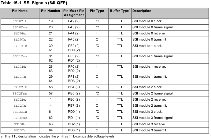
So i have two devices using SPI, a LCD screen and SD card (both have the same MOSI, MISO, SCK lines). I was looking at the card which came with my device and I noticed that SSI3 and SSI1 both share the same pins. However I can set a different CS. With that in mind I set up my code as follows:

#define LCD_SSI_BASE 				SSI3_BASE
#define NRF_SSI_BASE 				SSI2_BASE
#define SDC_SSI_BASE				SSI1_BASE

#define LCD_DC_SYSCTL_PERIPH   		SYSCTL_PERIPH_GPIOE

#define SSI1_GPIO_PORT_BASE_CS		GPIO_PORTF_BASE
#define SSI1_GPIO_PORT_BASE		GPIO_PORTD_BASE
#define SSI3_GPIO_PORT_BASE		GPIO_PORTD_BASE

#define SSI1SCK		GPIO_PD0_SSI1CLK
#define SSI1CS		GPIO_PF3_SSI1FSS
#define SSI1MISO	GPIO_PD2_SSI1RX
#define SSI1MOSI 	GPIO_PD3_SSI1TX

#define SSI3SCK		GPIO_PD0_SSI3CLK
#define SSI3CS		GPIO_PD1_SSI3FSS
#define SSI3MISO	GPIO_PD2_SSI3RX
#define SSI3MOSI 	GPIO_PD3_SSI3TX

#define LCD_DC_PORT_BASE 	GPIO_PORTE_BASE
#define LCD_DC_PIN GPIO_PIN_4

// clock
#define LCD_SCLK_PIN 	GPIO_PIN_0
#define LCD_MOSI_PIN 	GPIO_PIN_3
#define LCD_MISO_PIN 	GPIO_PIN_2
#define LCD_CS_PIN 	GPIO_PIN_1


void initTivaForLCD()
{
        SysCtlPeripheralEnable(SYSCTL_PERIPH_SSI3); // LCD
        SysCtlPeripheralEnable(SYSCTL_PERIPH_GPIOD); //LCD
	SysCtlPeripheralEnable (LCD_DC_SYSCTL_PERIPH);
	GPIOPinTypeGPIOOutput (LCD_DC_PORT_BASE, LCD_DC_PIN);
        GPIOPinConfigure(SSI3SCK);
	GPIOPinConfigure(SSI3CS);
	GPIOPinConfigure(SSI3MISO);
	GPIOPinConfigure(SSI3MOSI);
	GPIOPinTypeSSI(SSI3_GPIO_PORT_BASE, LCD_SCLK_PIN | LCD_MOSI_PIN | LCD_MISO_PIN | LCD_CS_PIN);
	ROM_SSIConfigSetExpClk (LCD_SSI_BASE, ROM_SysCtlClockGet (),
			                        SSI_FRF_MOTO_MODE_0, SSI_MODE_MASTER, 16000000, 8);
        ROM_SSIEnable (LCD_SSI_BASE);
	while(SSIDataGetNonBlocking(LCD_SSI_BASE, &ui32RcvDat))
			    {
			    }
}

void initTivaForSDC(void)
{
	SysCtlPeripheralDisable(SYSCTL_PERIPH_SSI3);
        SysCtlPeripheralEnable(SYSCTL_PERIPH_SSI1); // SDC
        SysCtlPeripheralEnable(SYSCTL_PERIPH_GPIOD); //LCD
        SysCtlPeripheralEnable(SYSCTL_PERIPH_GPIOF); // SDC CS
	GPIOPinConfigure(SSI1SCK);
	GPIOPinConfigure(SSI1CS);
	GPIOPinConfigure(SSI1MISO);
	GPIOPinConfigure(SSI1MOSI);
	GPIOPinTypeSSI(SSI1_GPIO_PORT_BASE, LCD_SCLK_PIN | LCD_MOSI_PIN | LCD_MISO_PIN | LCD_CS_PIN);
	GPIOPinTypeSSI(SSI1_GPIO_PORT_BASE_CS, SDC_CS_PIN);
	ROM_SSIConfigSetExpClk (SDC_SSI_BASE, ROM_SysCtlClockGet (),
			SSI_FRF_MOTO_MODE_0, SSI_MODE_MASTER, 400000, 8);
	ROM_SSIEnable (SDC_SSI_BASE);
	while(SSIDataGetNonBlocking(LCD_SSI_BASE, &ui32RcvDat))
				{
				}

}

My plan was to call one of the two above functions prior to using SPI. Note that they share MOSI, MISO and SCK pins but the CS is different.

However when i try to run this I end up in `FaultISR()` When I call `GPIOPinConfigure()` on a pin that has already been configured. Do i need to do a reconfigure or something?

  • Is it (really) true that 2 SPI Ports share the same pins?    Such seems odd - and w/out merit!     04:00 here - I ain't checking...

    And - if such a "clear Marketing ploy" does exist - why would hallowed vendor limit the selection to just TWO identical ports?    Why not TEN?   It must be then - that SSI_1 & SSI_3 are duplicated - upon (other) Ports/Pins - w/in your MCU.
     
    I do recall that "if" that "sharing of identical pins - by a "same family/style peripheral" occurs - that "ONLY ONE" will actually work!   (fog of memory indicates that's the "lower one.")    Might this describe - and explain - your (reported) plight?

    Move to a 2nd (non-shared) (i.e. "real/usable") SPI port seems most reasonable - n'est pas, mon ami?

  • I will bet my launchpad shirt that the SS1 and SS3 don't share the same pins!

    Could you please take a picture of said card?
    If you check the datasheet and this handy Energia pin out you will see that there aren't any shared pins between SSI
    energia.nu/.../tm4c123pinmap.png

    Anyway, even if that holds true, like cb1 said, do you really need to do that? Couldn't you just use other SSI?

    Btw I'm curious, in which GPIOPinConfigure did the fault ISR occur? Was it after executing it right?
  • Luis Afonso said:
    I will bet my launchpad shirt

    Careful there pal - 3rd world - 6 yr. olds - worked long/hard - creating that, "lo thread count shirt..."

  • The SD Card and Screen share a breakout so they share MOSI, MISO and SCK lines. So using two SPI interfaces which share wires or with a modifiable CS line is preferable.

    I am lookingat this document which came with my board. And youll notice SSI1 and SSI3 share some pins. (Highlighted)

  • Ah yes Jordy but notice, I think it's better seen in the datasheet:

    The SSI1 has multiple choices of pins! See now? 


    Btw, if you see in that paper there are some pins that have to GPIO there correct? You know why? PB7 is shorted with PD1 and PB6 is shorted with PD0 through 0-ohm resistors. If you want to use PB7 and PD1 or PB6 and PD0 at the same time, you will have to remove those resistors. Just a consideration for the future.


  • Ok. But since my LCD and SD card SPI devices share MOSI, MISO and SCK. I will have to short those pins? Seems like a bad thing to do...
  • cb1- said:
    It must be then - that SSI_1 & SSI_3 are duplicated - upon (other) Ports/Pins - w/in your MCU.

    Good response - (now) I've checked - and the statement I made earlier (quoted) is correct.    Note that SSI_1 appears across two different Ports - SSI_3 only one!

    Now - after reading your response - I can sense (some) advantage in your "switching" SSI peripherals - across the same pins.   Should each remote SPI device require different SPI data format - or clock rate - that could provide an advantage.

    But there's a, "fly in that ointment!"   By simply switching to a 2nd SPI peripheral - which attaches to the exact same MCU pins - how do you "fully/completely" de-activate or tri-state the "disabled" SPI peripheral?   That's required to prevent MCU peripheral contention - is it not?    Plus - the relative "rarity" of having 2 independent peripherals - share the same MCU pins - calls into question the skills & testing expertise required - to insure - that this (rare) method will work properly - under "all" conditions.    Is that clear.

    So - believe that explains your landing in the Fault ISR, "condition."    (although - if official boards exist - and "sanction this shared pin rarity" you (and I) may have "missed some detail."

    In the absence of (your) discovering & then complying with such detail(s) - I'd bet this would work by your full "Disabling" of the SPI port not in current use.   A call to function (similar to) SPI Port_x Disable may work.   (but you should probe the MCU's pins - both before & after - to insure that "residual SPI values/levels" do not persist!

    A surer method would be to both disable the previously enabled SPI port - then reset that peripheral (keeping it disabled) and then "Reconfigure the "new - now desired to function" SPI Port.   Such "pin sharing across peripherals" saves pins - but eats time/effort/money - I'd not go that route...

    [edit: just now saw Luis' response re those (delightful, so considerate) "PLAGUE 0Ω Rs!"    Indeed they'll (almost surely) wreck expected use of PD0/PD1!    Gotta go.   That said - your opening post (almost) suggested that you got ONE SPI periph. to work.   Method I've detailed here - should insure they both work - but only if you comply w/these rules - and use one at a time - and kill those idiot Rs.

  • No you shouldn't Jordi.

    You are saying that you basically have a board with and LCD and a SD card? Both being controlled by SPI correct? Then you should just use 1 SPI peripheral. What you need is a GPIO for each Chip select. The board should have a chip select for the LCD and the SD card. Ok wrong, apparently the SD card in SPI mode works in a different way. What I said was not wrong, you need only 1 SPI peripheral I assure you. But I have never used a SD card yet (when I tried I was pummeled by exams so...) so I can't help you much unfortunately.

    But still I'll leave you this since you seem to not know.
    When working with multiple SPI devices you can:
    Use 1 SPI peripheral per device or,
    If they are all the same (imagine all being a LED driver) they might have a cascading feature, you basically send n times the data that they take care of sending to each other in a cascade effect,
    You use 1 GPIO to act as the chip select pin, and you use it to select which device receives or gives the data on the SPI data lines, you have all the devices connected to the same SPI peripheral.

    Which board is it if I might ask?

  • Luis - you may note my post (few up) in which I described "why" the use of 2 SPI peripherals - appearing on the same MCU pins - (may) make sense! Its highly unusual - bit (retarded) - and "asks for trouble." (much like those delightful 0Ω plagues...)
  • Could I use SSI1, and swap the CS pin when i need to?