Because of the holidays, TI E2E™ design support forum responses will be delayed from Dec. 25 through Jan. 2. Thank you for your patience.

This thread has been locked.

If you have a related question, please click the "Ask a related question" button in the top right corner. The newly created question will be automatically linked to this question.

Running ISR from RAM.

Other Parts Discussed in Thread: EK-TM4C1294XL, TM4C123GH6PM, TM4C1294NCPDT

Hello again.

I'm using EK-TM4C1294XL board and CCS v5.5. I'd like to put my interrupt service routines code to RAM, so I can avoid ROM wait states and have ISR code executed faster. I know it can be done, I've read "Building Bare-Metal ARM Systems with GNU" by Miro Samek (you can google it), where author explains how to do it using GNU tools, which are little different form CCS's. I'm now working on porting Mr.Samek's solution to my project, but since I don't have much experience with linker scripts and bootloaders it will take me some time. So my question is this: does anyone have a working example of such code for CCS, and would like to share? Or maybe there's some TI's example, which I've not found?

  • I've two additional (non CCS centric) suggestions which may overlap or extend upon Mr. Samek's work.     (and thank you for providing that reference)   

    a) Joseph Yiu's books, "Definitive Guide to the Cortex (first M3, recently M0)    While not M4 - I believe his techniques have substantial "carry-over."

    b) more mature, refined & comprehensive IDEs such as Keil and IAR may better detail your objective - provide at minimum a "model" - which you can tweak.

    Our small tech firm cannot accept that one vendor - at all times - will have best/brightest MCUs - at superior price, feature, availability index.    IAR & Keil have long supported SWD (still absent here, iirc) and multiple vendor, ARM MCUs - enabling far broader choice - especially considering the (notable) absence of Cortex M0, M3 (RiP) and M7 - this space...

  • Thank you for your suggestions, I'm in possession of "The Definitive Guide to ARM Cortex-M3 and Cortex-M4 Processors, 3rd Edition" and read it briefly, and as far as I can see, it gives only a basic explanation about the matter. I'm bounded to CCS, my company bought license for it, so I do not have much of a choice.
  • Thanks your quick, keen response.      

    Its been years - but I have some recall that such was covered (possibly touched) by Mr. Yiu.    Not all of the chapter descriptions (fully) note what's (hidden) therein.     (i.e. that "definitive" tag may not extend to, "Table of Contents" chapter descriptions)

    As to IAR & Keil - I was about to further (i.e. better) explain my advice - there's no need to buy or even download a "free" version.      Both those mature, powerful IDEs have extensive written support - I believe available for free download.      As I think bit more - it may be that you must download the free version - and a "doc" folder is included - which holds a "treasure trove" of very clearly described - critical tech info.     (from my read of several of your posts - I'm reasonably sure you'd benefit - even if the "ISR from RAM" fails to "leap out.")

  • I'll give it a try then, thank you. But still, if someone have some code examples to share, It would be very appreciated.
  • Hi _BT_

    I know this is for the MSP430 but maybe you can use it with Tiva:
    embedded-funk.net/running-c-function-in-ram-on-msp430-devices
  • This looks very promising, I let you know if it worked. Thank you.
  • Hi _BT_, actually...

    Actually if you check your startup file you can see that the ISRs are configured with (note this is with TI compiler, not GCC):

    #pragma DATA_SECTION(g_pfnVectors, ".intvecs")

    See the .intvecs? That's in the .cmd file that should be in your folder. Mine is is TM4C123GH6PM.cmd:
    SECTIONS
    {
    .intvecs: > 0x00000000
    .text : > FLASH
    .const : > FLASH
    .cinit : > FLASH
    .pinit : > FLASH
    .init_array : > FLASH

    .vtable : > 0x20000000
    .data : > SRAM
    .bss : > SRAM
    .sysmem : > SRAM
    .stack : > SRAM
    }

    So if I am not mistaken, in the tm4c123gh6pm, the vector table size is 0x0268, so you should be able to set a symbol like:
    .intvect_ram > 0x20000270.

    I'm just "guessing", but maybe give it a try?


    This actually just changes the vector table array to start already at RAM. I tried to explain that in a post but because it was in a row it ended up going to automatic moderation (yay)

  • 2 more things,


    I've been checking and it seems that ".vtable" is already set. That's because when using TivaWare functions like IntRegister() it moves the vector table, that was before in ".intvecs" to ".vtable". So that's actually just the vector table (what I told you before was actually just moving the vector table to ram, not the functions - Sorry, failed).
    If I get more on the subject I'll come here again.


    If you're feeling like reading a lot:
    www.math.utah.edu/.../ld_3.html
    infocenter.arm.com/.../index.jsp
    infocenter.arm.com/.../DUI0474C_using_the_arm_linker.pdf
  • I think I got it _BT_

    The code successfully run without any problems and checked the .map and the function is in RAM address.

    Here is how my "section" looks like in the .cmd file:

    SECTIONS
    {
        .intvecs:   > 0x00000000
        .text   :   > FLASH
        .const  :   > FLASH
        .cinit  :   > FLASH
        .pinit  :   > FLASH
        .init_array : > FLASH
    
        .vtable :   > 0x20000000
        .ISR_RAM:   > 0x20000270
        .data   :   > SRAM
        .bss    :   > SRAM
        .sysmem :   > SRAM
        .stack  :   > SRAM
    }
    
    __STACK_TOP = __stack + 4096;

    If you notice I have a bigger stack than default but that is optional.
    Then I changed the startup file. I added to the vector table on the GPIOF the function "TesteF". Then above I added:

    #pragma CODE_SECTION(TesteF, ".ISR_RAM")
    void TesteF(){
    
        GPIOPinWrite(GPIO_PORTF_BASE,GPIO_PIN_1, GPIO_PIN_1);
    
    }

    And that's it. Notice that this is a blocking interrupt since it never clears the flag. Just for testing. The rest of the tests I'll leave them to you.
    Notice that on the .cmd file it seems easy to set the whole code to run from flash.


  • Nice, did you also check in debugger value of PC register when TesetF() is executed? I'll this try tomorrow at work(it's 9 pm here).

  • this day has been a bit too chaotic for me so not really :/

    I'll see if I can later (relax time) but not promises
  • Good enough _BT_ ;)


    Note that the Tivaware functions are not running from SRAM but instead they are in flash. You would have to configure the linker for that, use ROM functions or just use direct register access to take full advantage when using the ISR in RAM

  • _BT

     Your  ISR code won't run faster out from RAM. The RAM need to be coupled to core to be faster than Flash. (See CCM-RAM of the STM32F3). Furthermore the TM129x is almost zero wait states running from Flash.

     Ari.

  • Well, according to datasheet of the TM4C1294NCPDT (page 277, MEMTIM0 register description), when using 120MHz clock frequency, there are 5 wait states for flash memory.
  • Ari Mendes dos Santos said:
     Your  ISR code won't run faster out from RAM

    Is that true - over all conditions - at all times?    (I don't believe that statement will prove, "universal")

    Do note poster Luis' identification - that an ISR placed w/in RAM - may be "confounded/disadvantaged" - when (necessarily) calling functions which reside w/in Flash and (perhaps) ROM.    Has this factor received due consideration?

  • Yes it did. However I do not use any function calls inside ISR, only handful of assembly instructions. I've also noticed that in my case it was necessary to copy ISR's code from flash to ram "manually".
  • Hi _BT_

    Yes I was checking just that now. Suddenly came to mind "but wait... if the code is loaded into the RAM... what happens if I turn off the board?" .
    Have you been successful in copying the code from flash to RAM?
  • @ _BT_ Good that - and thank you - precise & quick response.

    Believe poster Luis has made a significant observation - which is sure to benefit those both, "rushed & not way solid in assembly!"

    Would you be so good as to report your "final findings" (ideally via identical ISRs - only difference being their placement) to the benefit of all who follow? Thanks.
  • I actually believe, if you are comfortable with assembly, that it would be easier to have a kinda bootloader function at the start of the code to copy the function from flash to RAM all made in assembly.
    If I find any other way I'll let you know.
  • Luis Afonso said:
    it would be easier to have a kinda bootloader function at the start of the code

    Mon ami - "Easier and bootloader" - in the same sentence - sacre bleu!

    Have not hundreds here - even those w/experience - crashed/burned (repeatedly) while trying to achieve a solid bootloader?

  • I am trying to suggest avoiding the bootloader.

    Maybe not the best wording, but was referring to the fact that it's a function that needs to always run at the start of the code and prepare part of the code (the part that goes into RAM).
    From the bootloader I want distance...
  • Usually called startup Luis.

    Sets up the execution environment before main or equivalent is called. Implementations range from simple to complex.

    Robert
  • Luis Afonso said:
    easier to have a kinda bootloader function

    This wording may not best suggest (or direct) avoidance of the bootloader!

    Good that you clarified.

    The whole technique (shift from "normal" code placement to placement w/in ram) really needs to be exercised and properly compared/contrasted.

    Only then - might it be possible/proper to see if the time/effort delivers (real) benefits - and to clearly identify, "Best and Worst application areas & conditions."

  • In both Tm4C123 and TM4C1294 it depends.

    Both have a pre fetch buffer. On the TM4C123 which is slower it seems there's just 1 wait state depending on some branches (the rest is 0 wait states.).
    In the TM4C1294 it works in a similar fashion though it seems to be a bit more complex. 0 wait state seems possible too.

    What about the ISR? Wouldn't there be some wait states at the start of the ISR to load the buffer and then when leaving it?
  • Much of this is (strictly) from the datasheets - if this extra effort is to be made - it would be nice to have some "real-world" data to confirm & possibly identify new issues or conflicts w/the datasheets and/or their presentation.   (i.e. "errata" is a known fact - usually signals performance "outside" the published data!)     Thus total reliance just on the "theoretical" (the data) may not prove "absolutely correct" in any/all instances...
     
    As an aside - I recall (at least for the 123 & earlier) that flash wait states varied (i.e. increased) w/system clock.   (penalizing highest speed operation)    I don't know - "if or how" - that continues with present day MCUs here.

    Again - not present in your latest writing - is it not instructive to compare ISR execution - w/in RAM and Flash - to see if such detailed time/effort has (any) real payoff?     (as small biz guy - we (always) must justify such investigations - insure there's (reasonable) pay-off!)

  • I'm not by any means proficient in assembly. I'm using it only for simple tasks such as writing registers to switch pin state or clear interrupt, and that's in fact what my ISR is doing.

    As soon as I'll have solid and repetitive results, I'll let you all know. Tomorrow probably, if I find the time at work.

  • Can I advise you something _BT_?

    The linker command to load the ISR into the RAM right? So test that way if it's worth it all the work your gonna have. I would say this is better than trying to figure out a way to copy the code from flash to sram and find out that it's not an improvement or it's not worth it when you already have a easier, known way to test it.
    Don't you think the same?
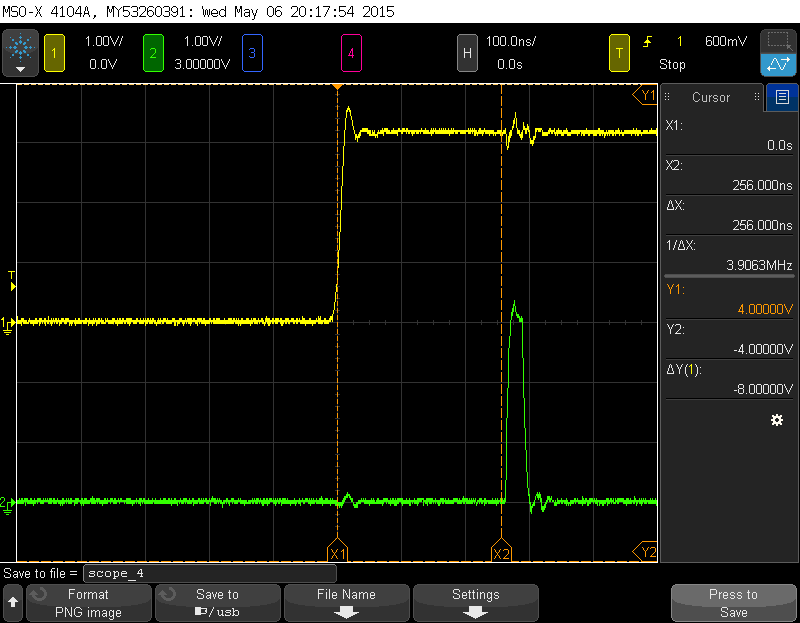
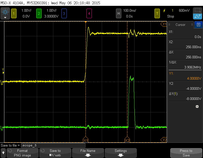
  • Well, it wasn't particularly difficult to copy code from flash to ram, all what one needs to do, is to know source and destination addresses and call memcpy() or similar function. As about delays, well, I'm a little disappointed, there's not much of a difference if code is executed from flash memory or sram.

  • a little disappointed? Or maybe admired?

    The pre-fetch buffer should only had some cycles (don't know how many it is to fetch more) at the beginning of the ISR, then the rest of the ISR should be pretty much 0 wait cycles (depending on the branches) and then at the end of the ISR, back to the main, there should be some more wait cycles to fill the buffer again. So yea, it's probably because of that.

    How many cycles did you improve?
  • Maybe I did not expressed myself clearly, I was hoping that moving ISR code from flash to ram will shorten the delay, but it did not. There's no improvement.
  • You said "not much of a difference" so I thought there was like 1-5 cycles improvement.
  • _BT_ said:
    As about delays, well, I'm a little disappointed, there's not much of a difference if code is executed from flash memory or sram.

    Thanks much for this report my friend - surely helpful (and time-saving) to many.

    Recall your opening post - in which the "reduced execution time" was touted.    Such "theory" does not always survive the "real world" - no matter how much we hope/pray.

    Might you detail just how you made your "ISR's execution time" measurements?     Ideally - methods should have been identical (and that alone may describe why any "gain" was lost/compromised!)

    Thanks again your report - may we assume your code now (all) moves to normal Flash?

  • Sure. My ISR code is written in assembly, it looks like this:

    #pragma CODE_SECTION(PNO_Int_Handler_Rising, ".ram_code")
    void PNO_Int_Handler_Rising(void) { __asm( " movw r0, #0x33FC\n" /* lower part of port M address plus required bitmask 0x3FC to r0*/ " movt r0, #0x4006\n" /* top part of the address */ " sub r1, r0, #0xB000\n" /* port A address to r1*/ " mov r2, #0x20\n" /* pm5 pin value to r2*/ " mov r3, #0xFF\n" /* all pins of port A */ " str r2, [r0]\n" /* write to port M*/ " str r3, [r1]\n" /* write to port A*/ " mov r2, #0x0\n" /* write 0 to set pins to low state*/ " str r2, [r0]\n" /* write port M*/ " str r2, [r1]\n" /* write port A*/ " movw r0, #0x641C\n" /* clear interrupt source, first write address of register to r0 */ " movt r0, #0x4006\n" " mov r1, #0xff\n" /* interrupt is cleared by writing 1" */ " str r1, [r0]\n" /* write to interrupt clear register */ ); }

    To load interrupt code to ram I've modified default linker script to this :

    #define APP_BASE 0x00000000
    #define RAM_BASE 0x20000000
    
    #define RAM_CODE_START_ADDR             (0x20000000)
    #define RAM_CODE_END_ADDR               (0x20007FFF)
    #define RAM_CODE_LEN                    (0x8000)
    
    #define RAM_DATA_START_ADDR             (0x20008000)
    #define RAM_DATA_END_ADDR               (0x2003FFFF)
    #define RAM_DATA_LEN                    (0x00040000)
    
    #define FLASH_RAM_CODE_START_ADDR       (0x00000000)
    #define FLASH_RAM_CODE_END_ADDR         (0x00007FFF)
    #define FLASH_RAM_CODE_LEN              (0x00008000)
    
    #define FLASH_START_ADDR                (0x00008000)
    #define FLASH_END_ADDR                  (FFFFF)
    #define FLASH_LEN                       (0x00100000)
    
    
    /* System memory map */
    
    MEMORY
    {
    
        FLASH_RAM_CODE (RX)         : origin = FLASH_RAM_CODE_START_ADDR, length = FLASH_RAM_CODE_LEN
        FLASH          (RX)		: origin = FLASH_START_ADDR, length = FLASH_LEN
        RAM_CODE       (RWX)	: origin = RAM_CODE_START_ADDR, length = RAM_CODE_LEN
        RAM	           (RWX)	: origin = RAM_DATA_START_ADDR, length = RAM_DATA_LEN
    }
    
    /* Section allocation in memory */
    
    SECTIONS
    {
        .intvecs:   > APP_BASE
        .text	:	> FLASH
        .const  :   > FLASH
        .cinit  :   > FLASH
        .pinit  :   > FLASH
        .init_array : > FLASH
    
        .vtable :   > RAM_BASE
        .data   :   > RAM
        .bss    :   > RAM
        .sysmem :   > RAM
        .stack  :   > RAM
        .ram_code : load = FLASH_RAM_CODE, run = RAM_CODE
    }
    
    __STACK_TOP = __stack + 1024;

    And this call as first function in main():

        my_memcpy(((void*)0x20000000), ((void*)0x200), 0x262);

    Which copies ISR's code from flash to ram.

    All what's left was to measure impulses on a scope, first ISR run from ram:

    And this what it's looks like when code is executed from flash:

    And yes, from now on code will be executed from flash only.

  • We need to ask Amit how to rank a post (above) 10! Absolutely spectacular!

    Yet - as my group has been at this for awhile - the "exact duplication" of your results rings an alarm. (at least a lowered one)

    I'm not smart/quick enough to properly diagnose - but I've concern that the time between "trigger event" and "return from interrupt" may not (really) be properly measured. (such concern "solely" due to the exact match your caps convey - in the real-world - such exactness (most always) will not occur...)

    Again - great job...

    Would be useful if posters Robert, Veikko and the charging Luis - and of course the "boss" would check-in/comment...

  • A couple of notes I can add

    • The outputs themselves can add significantly to the timing.  I don't think that's the case with this processor but it does sometimes happen that I/O takes long enough to mask cache activity.
    • The cache may well work to confound your measurements. It's one reason embedded developers have resisted cache, it makes timing difficult to impossible to predict.  I don't know if the cache behaves this way and I don't remember the cache behaviour even being documented (it's often considered proprietary) but consider the following possibilities
      • The entire program, including the in-flash interrupt routine is small enough that it fits into the prefetched cache lines (cache often reads ahead of program execution). The interrupt then effectively is executed directly out of the cache. Side note: in this case if there were any delay in reading RAM then running from flash would actually be faster
      • Or, the interrupt is small and the main test program is either small or contains no address that would cause the interrupt cache line to be flushed. In that case after the first execution the interrupt may remain cached and execute directly out of the cache.

    This is a set of entirely hypothetical thoughts.  I think you've done enough to suggest that RAM execution is at least a third order optimization.  First is algorithm, second is implementation, third is location. I don't think you can be definitive w/o taking measurements on a full (or nearly so) application and then I'd only do it in the face of an actual need for this kind on micro-optimization.

    Robert

    And if the instruction cache is not limited to flash, there's a whole other layer of complication.

    Also: agreed cb1, nice measurement.

  • May this reporter - (now) note - the occurrence of a second 10+ post?      I'm "out" of (non-repeating) adjectives thus - "C'est tres bien!    Merci.

    And Robert - do you not agree that the "exact duplication" of execution proves disturbing - led to your many (suggested) events - "behind the curtain?"

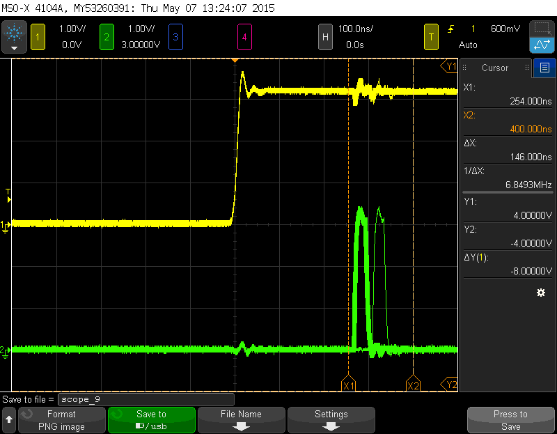
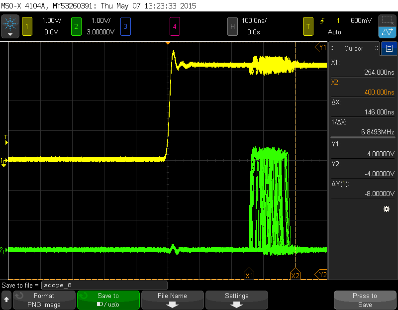
  • Here's something interesting, when doing my last measurements, after configuring hardware ant interrupts my application just entered simple while(1); loop and did nothing. But as Robert suggested that cache could have large impact on execution speeds, I've decided to add some more code to main loop. Here are the results of my observations, first ISR run from flash:

    As you can see, from time to time there's difference in response time. And it varies, I could not catch it on a scope, but those differences fit between X1 and X2 markers. But what's happening when code is run from ram, is even more "disturbing":

    Interesting, is it not?

    I've also marked my previous post as answer to my original question, since I've asked, how to load code into ram, and I believe with Louis help I've manage to do that.

  • Appears (once again) that poster Robert has "topped" this class.

    And - while "Louis" thought about helping - "Luis" in fact jumped to your aid - deserves full credit.      (in fairness - I'd tick green for Robert's "inspired, behind the scenes" explanation - as well!)

    Your continued update is appreciated - you've rewarded your helpers w/most excellent feedback & "real" data dump - thank you...

  • I've been called Louis lots of times, most of my friends back at home called me that (somehow it stick, I don't remember where that extra "o" came from)

    Which scope do you use _BT_? Is it like most tektronix that saves to a pen drive or can it have interface with the PC? I've been wanting one that interfaces with the PC to the club. I have my eyes on Saleae but I could change my mind.

    That snapshot when running from RAM is weird. It seems the ISR was called multiple times? I assume that the interrupt event was a rising edge on a input?

    Just 1 question, would not having a breakpoint at the beginning of the ISR and other at the end in conjunction with a cycle counter prove to be a better test? I know IAR has it and CCS appears to have it as well. While the scope allows the measure the delay between getting the rising edge and reaching the part of the ISR where it toggles the pin, it does not give full ISR execution time.
  • _BT_ said:
    Interesting, is it not?

    Welcome to interrupt jitter.

    Contributing sources

    • variable instruction timing (probably not an issue in your simple original loop)
    • caching behaviour
    • critical sections
    • other interrupts
    • asynchrony

    You might have to capture a lot of events to see the full range of possible latencies.  Sometimes just because of link layout or the way the program executes or some synchronous timing between the program and the interrupt source some latencies are a lot more probable than others.

    Robert

  • Sorry for misspelling your name. I use Agilent MOS-X 4104A, to save a snapshot I use a pendrive.
    It's not like an ISR was called multiple times, digital oscilloscopes when running in continuous trigger mode shows a "stack" of multiple measurements if a time between each trigger is short (in this case rising edge of yellow signal occurs every 300 us). If I would take a single measurement I would always get a single impulse on green channel.
    As about testing, for me it's most important to have knowledge about response time on output to a triggering signal, I do not "care" how many cycles it takes, and for that scope is a perfect tool.
  • _BT_ said:
    it's most important to have knowledge about response time on output to a triggering signal

    Very well explained - yet (while you know) others (here) may benefit from poster Robert's alert that. "any such response time may have "program dependencies" - which (may) cause "deviation" from "response time" expectations!     Suspect that when "near absolute" response times are mandated - program execution must be constrained - to prevent unwanted deviations...