Other Parts Discussed in Thread: TCA6416A, TCA6507
Subjet: I2C question between TCA6416A and TM4C129DB board
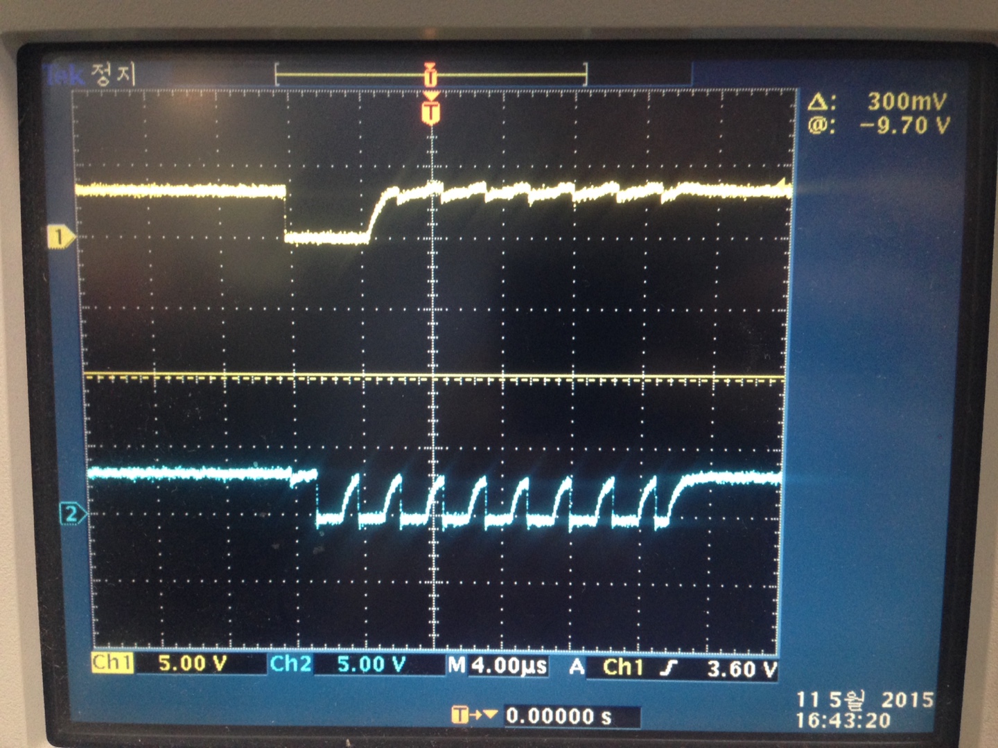
I am using to TCA6416A and TM4C129DB board , but I2C_MASTER_ERR_ARB_LOST is generated by I2CMasterErr(ulI2CBase).
help me !
#ifndef __I2C_API_H__
#define __I2C_API_H__
//*****************************************************************************
//
// Device parameters. Here you will need to define the I2C address for the
// specific part. It needs to be in following format:
//
// [A6]:[A5]:[A4]:[A3]:[A2]:[A1]:[A0]:[X]
//
//*****************************************************************************
#define DEVICE_ADDRESS 0x40
//*****************************************************************************
//
// I2C peripheral number definitions. These values are used for the
// ulI2CPeriph parameter.
//
//*****************************************************************************
#define I2C_PERIPH_0 0
#define I2C_PERIPH_1 1
#define I2C_LNA_PA 0x02
#define I2C_BUZZER 0x04
#define I2C_LED1 0x08
#define I2C_LED2 0x10
#define I2C_LCD_BACKLIGHT 0x20
#define I2C_GPS 0x40
#define I2C_CODEC 0x80
//*****************************************************************************
//
// Prototypes for the APIs.
//
//*****************************************************************************
extern void I2CInit(unsigned long ulI2CPeriph,
unsigned long ulI2CSpeed);
extern unsigned long I2CRegRead(unsigned long ulI2CBase,
unsigned char ucReg);
extern unsigned long I2CRegWrite(unsigned long ulI2CBase,
unsigned char ucReg,
unsigned char ucValue);
#endif // __I2C_API_H__
\\\\\\\\\\\\\\\\\\\\\\\\\\\\\\\\\\\\\\\\\\\\\\\\\\\\\\\\\\\\\\\\\\\\\\\\\\\\\\\\\\\\\\\\\\\\\
//*****************************************************************
//
// i2c_api.c
//
//
// by jae hyoung Lee, 2015.05.08
//********************************************************************
#include <stdbool.h>
#include <stdint.h>
#include <stdio.h>
#include "inc/hw_memmap.h"
#include "inc/hw_types.h"
#include "driverlib/i2c.h"
#include "driverlib/debug.h"
#include "i2c_api.h"
#include "driverlib/sysctl.h"
#include "driverlib/uart.h"
#include "utils/uartstdio.h"
//******************************************
//
// Initializes and enables the specified I2C block.
//************************************************
void
I2CInit(unsigned long ulI2CPeriph, unsigned long ulI2CSpeed)
{
//
// Check the arguments.
//
ASSERT((ulI2CPeriph == I2C_PERIPH_0) || (ulI2CPeriph == I2C_PERIPH_1));
ASSERT((ulI2CSpeed == true) || (ulI2CSpeed == false));
//
// Enable and initialize the appropriate I2C block.
//
if(!ulI2CPeriph)
{
//
// The I2C0 peripheral must be enabled before use.
//
SysCtlPeripheralReset(SYSCTL_PERIPH_I2C0);
SysCtlPeripheralEnable(SYSCTL_PERIPH_I2C0);
//
// Enable and initialize the I2C0 master module.
//
I2CMasterInitExpClk(I2C0_BASE, SysCtlClockGet(), ulI2CSpeed);
SysCtlDelay(10000);
}
else
{
SysCtlPeripheralReset(SYSCTL_PERIPH_I2C1);
//
// The I2C1 peripheral must be enabled before use.
//
SysCtlPeripheralEnable(SYSCTL_PERIPH_I2C1);
//
// Enable and initialize the I2C1 master module.
//
I2CMasterInitExpClk(I2C0_BASE, SysCtlClockGet(), ulI2CSpeed);
SysCtlDelay(10000);
}
}
//*****************************************************************************
//
//! Reads the specified TCAxxxx register.
//!
//! \param ulI2CBase is the base for the I2C module.
//! \param ucReg is the resgister to read from.
//!
//! This function initiates a read from the TCAxxxx. The ulI2CBase parameter
//! is the I2C modules master base address. The \e ulI2CBase parameter can
//! be one of the following values:
//!
//! - I2C0_BASE
//! - I2C1_MASTER_BASE
//!
//! \return Register value in an unsigned long foramt. Note that 0 will be
//! returned if there is ever an error.
//
//*****************************************************************************
unsigned long
I2CRegRead(unsigned long ulI2CBase, unsigned char ucReg)
{
unsigned long ulRegValue = 0;
//
// Check the arguments.
//
ASSERT((ulI2CBase == I2C0_BASE) || (ulI2CBase == I2C0_BASE));
//
// Tell the master module what address it will place on the bus when
// writing to the slave.
//
I2CMasterSlaveAddrSet(ulI2CBase, (DEVICE_ADDRESS>>1), 0);
//
// Place the command to be sent in the data register.
//
I2CMasterDataPut(ulI2CBase, ucReg);
//
// Initiate send of data from the master.
//
I2CMasterControl(ulI2CBase, I2C_MASTER_CMD_SINGLE_SEND);
//
// Wait until master module is done transferring.
//
while(I2CMasterBusy(ulI2CBase))
{
UARTprintf("I2C transferring 1-> I2C reading..... \n");
}
//
// Check for errors.
//
if(I2CMasterErr(ulI2CBase) != I2C_MASTER_ERR_NONE)
{
UARTprintf("I2C transferring 1-> error \n");
return 0;
}
//
// Tell the master module what address it will place on the bus when
// reading from the slave.
//
I2CMasterSlaveAddrSet(ulI2CBase, (DEVICE_ADDRESS>>1), 1);
//
// Tell the master to read data.
//
I2CMasterControl(ulI2CBase, I2C_MASTER_CMD_SINGLE_RECEIVE);
//
// Wait until master module is done receiving.
//
while(I2CMasterBusy(ulI2CBase))
{
UARTprintf("I2C transferring 2-> I2C reading..... \n");
}
//
// Check for errors.
//
if(I2CMasterErr(ulI2CBase) != I2C_MASTER_ERR_NONE)
{
UARTprintf("I2C transferring 2-> error \n");
return 0;
}
//
// Read the data from the master.
//
ulRegValue = I2CMasterDataGet(ulI2CBase);
//
// Return the register value.
//
return ulRegValue;
}
//*****************************************************************************
//
//! Writes to the specifed TCAxxxx register.
//!
//! \param ulI2CBase is the base for the I2C module.
//! \param ucReg is the register to write data to.
//! \param ucValue is the 8-bit data to be written.
//!
//! This function initiates a read from the TCAxxxx device.
//!
//! \return 0 if there was an error or 1 if there was not.
//
//*****************************************************************************
unsigned long
I2CRegWrite(unsigned long ulI2CBase, unsigned char ucReg,
unsigned char ucValue)
{
//
// Check the arguments.
//
ASSERT((ulI2CBase == I2C0_BASE) || (ulI2CBase == I2C1_MASTER_BASE));
//
// Tell the master module what address it will place on the bus when
// writing to the slave.
//
uint8_t temp_addr =(DEVICE_ADDRESS>>1);
I2CMasterSlaveAddrSet(ulI2CBase, (DEVICE_ADDRESS>>1), 0); //0: master가 slave에 쓰기 한다. 1: 읽기
UARTprintf("I2C Address:%X \n",temp_addr );
// Initiate send of data from the master.
//
// Place the command to be sent in the data register.
//
I2CMasterDataPut(ulI2CBase, ucReg);
UARTprintf("I2C mater->slave : %x\n",ucReg);
//
I2CMasterControl(ulI2CBase, I2C_MASTER_CMD_BURST_SEND_START);
//
//
// Wait until master module is done transferring.
//
while(I2CMasterBusy(ulI2CBase))
{
UARTprintf( "transferring 1-> I2C command writing.:0x%1X, busy return value:%d \n",ucReg, I2CMasterBusy(ulI2CBase));
}
//
// Check for errors.
//
if(I2CMasterErr(ulI2CBase) != I2C_MASTER_ERR_NONE)
{
UARTprintf("I2C transferring 1-> error valu: %x \n",I2CMasterErr(ulI2CBase) );
return 0;
}
//
// Place the value to be sent in the data register.
//
I2CMasterDataPut(ulI2CBase, ucValue);
//
// Initiate send of data from the master.
//
I2CMasterControl(ulI2CBase, I2C_MASTER_CMD_BURST_SEND_FINISH);
//
// Wait until master module is done transferring.
//
while(I2CMasterBusy(ulI2CBase))
{
UARTprintf("I2C transferring 2-> I2C value writing...5%X \n",ucValue );
}
//
// Check for errors.
//
if(I2CMasterErr(ulI2CBase) != I2C_MASTER_ERR_NONE)
{
UARTprintf("I2C transferring 2-> error \n");
return 0;
}
//
// Initiate send of data from the master.
//
// I2CMasterControl(ulI2CBase, I2C_MASTER_CMD_BURST_SEND_FINISH);
//
// Wait until master module is done transferring.
//
while(I2CMasterBusy(ulI2CBase))
{
UARTprintf("I2C transferring 2-> I2C writing..... \n");
}
//
// Check for errors.
//
if(I2CMasterErr(ulI2CBase) != I2C_MASTER_ERR_NONE)
{
return 0;
}
//
// Return 1 if there is no errors.
//
return 1;
}
\\\\\\\\\\\\\\\\\\\\\\\\\\\\\\\\\\\\\\\\\\\\\\\\\\\\\\\\
//*****************************************************************************
//
// master__loopback.c - Example demonstrating a simple I2C message
// transmission and reception.
//
// Copyright (c) 2010-2013 Texas Instruments Incorporated. All rights reserved.
// Software License Agreement
//
// Redistribution and use in source and binary forms, with or without
// modification, are permitted provided that the following conditions
// are met:
//
// Redistributions of source code must retain the above copyright
// notice, this list of conditions and the following disclaimer.
//
// Redistributions in binary form must reproduce the above copyright
// notice, this list of conditions and the following disclaimer in the
// documentation and/or other materials provided with the
// distribution.
//
// Neither the name of Texas Instruments Incorporated nor the names of
// its contributors may be used to endorse or promote products derived
// from this software without specific prior written permission.
//
// THIS SOFTWARE IS PROVIDED BY THE COPYRIGHT HOLDERS AND CONTRIBUTORS
// "AS IS" AND ANY EXPRESS OR IMPLIED WARRANTIES, INCLUDING, BUT NOT
// LIMITED TO, THE IMPLIED WARRANTIES OF MERCHANTABILITY AND FITNESS FOR
// A PARTICULAR PURPOSE ARE DISCLAIMED. IN NO EVENT SHALL THE COPYRIGHT
// OWNER OR CONTRIBUTORS BE LIABLE FOR ANY DIRECT, INDIRECT, INCIDENTAL,
// SPECIAL, EXEMPLARY, OR CONSEQUENTIAL DAMAGES (INCLUDING, BUT NOT
// LIMITED TO, PROCUREMENT OF SUBSTITUTE GOODS OR SERVICES; LOSS OF USE,
// DATA, OR PROFITS; OR BUSINESS INTERRUPTION) HOWEVER CAUSED AND ON ANY
// THEORY OF LIABILITY, WHETHER IN CONTRACT, STRICT LIABILITY, OR TORT
// (INCLUDING NEGLIGENCE OR OTHERWISE) ARISING IN ANY WAY OUT OF THE USE
// OF THIS SOFTWARE, EVEN IF ADVISED OF THE POSSIBILITY OF SUCH DAMAGE.
//
// This is part of revision 2.0.1.11577 of the Tiva Firmware Development Package.
//
//*****************************************************************************
#include <stdbool.h>
#include <stdint.h>
#include <stdio.h>
#include "inc/hw_i2c.h"
#include "inc/hw_memmap.h"
#include "inc/hw_types.h"
#include "driverlib/gpio.h"
#include "driverlib/i2c.h"
#include "driverlib/pin_map.h"
#include "driverlib/sysctl.h"
#include "i2c_api.h"
#include "driverlib/uart.h"
#include "utils/uartstdio.h"
//*****************************************************************************
//
//! \addtogroup i2c_examples_list
//! <h1>I2C Master Loopback (i2c_master_slave_loopback)</h1>
//!
//! This example shows how to configure the I2C0 module for loopback mode.
//! This includes setting up the master and slave module. Loopback mode
//! internally connects the master and slave data and clock lines together.
//! The address of the slave module is set in order to read data from the
//! master. Then the data is checked to make sure the received data matches
//! the data that was transmitted. This example uses a polling method for
//! sending and receiving data.
//!
//! This example uses the following peripherals and I/O signals. You must
//! review these and change as needed for your own board:
//! - I2C0 peripheral
//! - GPIO Port B peripheral (for I2C0 pins)
//! - I2C0SCL - PB2
//! - I2C0SDA - PB3
//!
//! The following UART signals are configured only for displaying console
//! messages for this example. These are not required for operation of I2C.
//! - UART0 peripheral
//! - GPIO Port A peripheral (for UART0 pins)
//! - UART0RX - PA0
//! - UART0TX - PA1
//!
//! This example uses the following interrupt handlers. To use this example
//! in your own application you must add these interrupt handlers to your
//! vector table.
//! - None.
//
//*****************************************************************************
//*****************************************************************************
//
// Register command definitions. These are the values that can be used for the
// ucReg parameter. Reference the TCA6507 datasheet for more information on
// registers and values.
//
//*****************************************************************************
#define REG_INPUT_PORT0 0x00
#define REG_INPUT_PORT1 0x01
#define REG_OUTPUT_PORT0 0x02
#define REG_OUTPUT_PORT1 0x03
#define REG_POLARITY_INVERSION_PORT0 0x04
#define REG_POLARITY_INVERSION_PORT1 0x05
#define CONFIGURATION_PORT0 0x06
#define CONFIGURATION_PORT1 0x07
//*****************************************************************************
//*****************************************************************************
//
// 8-bit variables to read registers.
//
//*****************************************************************************
//static unsigned char ucRegReadOrig = 0;
//static unsigned char ucRegReadNew = 0;
//*****************************************************************************
//
// Set the address for slave module. This is a 7-bit address sent in the
// following format:
// [A6:A5:A4:A3:A2:A1:A0:RS]
//
// A zero in the "RS" position of the first byte means that the master
// transmits (sends) data to the selected slave, and a one in this position
// means that the master receives data from the slave.
//
//*****************************************************************************
// #define SLAVE_ADDRESS 0x3C
//#define SLAVE_ADDRESS 0x40
//*****************************************************************************
//
// This function sets up UART0 to be used for a console to display information
// as the example is running.
//
//*****************************************************************************
void
InitConsole(void)
{
//
// Enable GPIO port A which is used for UART0 pins.
// TODO: change this to whichever GPIO port you are using.
//
SysCtlPeripheralEnable(SYSCTL_PERIPH_GPIOA);
//
// Configure the pin muxing for UART0 functions on port A0 and A1.
// This step is not necessary if your part does not support pin muxing.
// TODO: change this to select the port/pin you are using.
//
GPIOPinConfigure(GPIO_PA0_U0RX);
GPIOPinConfigure(GPIO_PA1_U0TX);
//
// Enable UART0 so that we can configure the clock.
//
SysCtlPeripheralEnable(SYSCTL_PERIPH_UART0);
//
// Use the internal 16MHz oscillator as the UART clock source.
//
UARTClockSourceSet(UART0_BASE, UART_CLOCK_PIOSC);
//
// Select the alternate (UART) function for these pins.
// TODO: change this to select the port/pin you are using.
//
GPIOPinTypeUART(GPIO_PORTA_BASE, GPIO_PIN_0 | GPIO_PIN_1);
//
// Initialize the UART for console I/O.
//
UARTStdioConfig(0, 115200, 16000000);
}
//*****************************************************************************
//
// Configure the I2C0 master and slave and connect them using loopback mode.
//
//*****************************************************************************
int
main(void)
{
//
// Set the clocking to run directly from the crystal.
//
// TODO: change this to specific crystal value on your board.
//
SysCtlClockSet(SYSCTL_SYSDIV_1 | SYSCTL_USE_OSC | SYSCTL_OSC_MAIN |
SYSCTL_XTAL_8MHZ);
//
// For this example I2C0 is used with PortB[3:2]. The actual port and
// pins used may be different on your part, consult the data sheet for
// more information. GPIO port B needs to be enabled so these pins can
// be used.
//
// TODO: change this to whichever GPIO port you are using.
//
SysCtlPeripheralEnable(SYSCTL_PERIPH_GPIOB);
//
// Configure the pin muxing for I2C0 functions on port B2 and B3.
// This step is not necessary if your part does not support pin muxing.
//
// TODO: change this to select the port/pin you are using.
//
GPIOPinConfigure(GPIO_PB2_I2C0SCL);
GPIOPinConfigure(GPIO_PB3_I2C0SDA);
//
// Select the I2C function for these pins. This function will also
// configure the GPIO pins for I2C operation, setting them to
// open-drain operation with weak pull-ups. Consult the data sheet
// to see which functions are allocated per pin.
//
// TODO: change this to select the port/pin you are using.
//
GPIOPinTypeI2C(GPIO_PORTB_BASE, GPIO_PIN_2 | GPIO_PIN_3);
I2CInit(I2C_PERIPH_0, true); //treu: 400kHz , false : 100kHz
GPIOPadConfigSet(GPIO_PORTB_BASE, GPIO_PIN_2 | GPIO_PIN_3,GPIO_STRENGTH_2MA,GPIO_PIN_TYPE_STD ); //반드시 들어가야하는것 같음 이거 안너흐면 while문에서 못빠져 나옴
HWREG(I2C0_BASE + I2C_O_MCR) |= I2C_MCR_MFE; // I2C Master Function Enable //추가호가인필요
I2CMasterEnable(I2C0_BASE);//추가호가인필요
// I2CSlaveInit(I2C0_BASE, SLAVE_ADDRESS);//추가호가인필요
// Initialize the I2C interface to talk to the TCAxxxx board. The false
// paramter specifies a I2C speed of 100kbps.
//
InitConsole(); // serial communication initialization
if(I2CRegWrite(I2C0_BASE, REG_OUTPUT_PORT0, I2C_CODEC|I2C_LCD_BACKLIGHT|I2C_LNA_PA)==1) // active to codec OPAMP 0x80|0x20|0x02
UARTprintf("I2C transferring compleate...\n");
else UARTprintf("I2C transferring fail...\n");
if(I2CRegWrite(I2C0_BASE, REG_OUTPUT_PORT0, I2C_CODEC|I2C_LCD_BACKLIGHT|I2C_LNA_PA)==1) // active to codec OPAMP 0x80|0x20|0x02
UARTprintf("I2C transferring compleate...\n");
else UARTprintf("I2C transferring fail...\n") ;
return(0);
}