


Dear Sir/Madam,
I have been working with the TMDXTMS570LS12CNCD controlcard during the past two week without any problem at all, but eventualy a couple days ago trying to load a new program I encountered the following error:
Error connecting to the target:
(Error -1170 @ 0x0)
Unable to access the DAP. Reset the device, and retry the operation. If error persists, confirm configuration, power-cycle the board, and/or try more reliable JTAG settings (e.g. lower TCLK).
(Emulation package 0.0.0.0)
I tried to reset the device and the error continued. Also there is no problem with the TCLK since it is using the default value (1MHz) and I have tried with lower values as well and the problem remained.
I shall remark that the controlboard was working well up to this point. Also the Test Connection in Target Configuration has never reported any error (not even now) and it reports the following log:
[Start: Texas Instruments XDS100v2 USB Debug Probe_0]
Execute the command:
%ccs_base%/common/uscif/dbgjtag -f %boarddatafile% -rv -o -F inform,logfile=yes -S pathlength -S integrity
[Result]
-----[Print the board config pathname(s)]------------------------------------
C:\Users\WILLIA~1\AppData\Local\TEXASI~1\
CCS\ti\0\0\BrdDat\testBoard.dat
-----[Print the reset-command software log-file]-----------------------------
This utility has selected a 100- or 510-class product.
This utility will load the adapter 'jioserdesusb.dll'.
The library build date was 'Feb 18 2015'.
The library build time was '23:56:50'.
The library package version is '5.1.641.0'.
The library component version is '35.34.40.0'.
The controller does not use a programmable FPGA.
The controller has a version number of '4' (0x00000004).
The controller has an insertion length of '0' (0x00000000).
This utility will attempt to reset the controller.
This utility has successfully reset the controller.
-----[Print the reset-command hardware log-file]-----------------------------
The scan-path will be reset by toggling the JTAG TRST signal.
The controller is the FTDI FT2232 with USB interface.
The link from controller to target is direct (without cable).
The software is configured for FTDI FT2232 features.
The controller cannot monitor the value on the EMU[0] pin.
The controller cannot monitor the value on the EMU[1] pin.
The controller cannot control the timing on output pins.
The controller cannot control the timing on input pins.
The scan-path link-delay has been set to exactly '0' (0x0000).
-----[The log-file for the JTAG TCLK output generated from the PLL]----------
There is no hardware for programming the JTAG TCLK frequency.
-----[Measure the source and frequency of the final JTAG TCLKR input]--------
There is no hardware for measuring the JTAG TCLK frequency.
-----[Perform the standard path-length test on the JTAG IR and DR]-----------
This path-length test uses blocks of 512 32-bit words.
The test for the JTAG IR instruction path-length succeeded.
The JTAG IR instruction path-length is 6 bits.
The test for the JTAG DR bypass path-length succeeded.
The JTAG DR bypass path-length is 1 bits.
-----[Perform the Integrity scan-test on the JTAG IR]------------------------
This test will use blocks of 512 32-bit words.
This test will be applied just once.
Do a test using 0xFFFFFFFF.
Scan tests: 1, skipped: 0, failed: 0
Do a test using 0x00000000.
Scan tests: 2, skipped: 0, failed: 0
Do a test using 0xFE03E0E2.
Scan tests: 3, skipped: 0, failed: 0
Do a test using 0x01FC1F1D.
Scan tests: 4, skipped: 0, failed: 0
Do a test using 0x5533CCAA.
Scan tests: 5, skipped: 0, failed: 0
Do a test using 0xAACC3355.
Scan tests: 6, skipped: 0, failed: 0
All of the values were scanned correctly.
The JTAG IR Integrity scan-test has succeeded.
-----[Perform the Integrity scan-test on the JTAG DR]------------------------
This test will use blocks of 512 32-bit words.
This test will be applied just once.
Do a test using 0xFFFFFFFF.
Scan tests: 1, skipped: 0, failed: 0
Do a test using 0x00000000.
Scan tests: 2, skipped: 0, failed: 0
Do a test using 0xFE03E0E2.
Scan tests: 3, skipped: 0, failed: 0
Do a test using 0x01FC1F1D.
Scan tests: 4, skipped: 0, failed: 0
Do a test using 0x5533CCAA.
Scan tests: 5, skipped: 0, failed: 0
Do a test using 0xAACC3355.
Scan tests: 6, skipped: 0, failed: 0
All of the values were scanned correctly.
The JTAG DR Integrity scan-test has succeeded.
[End: Texas Instruments XDS100v2 USB Debug Probe_0]
I looked into it in the forum and I found the following post:
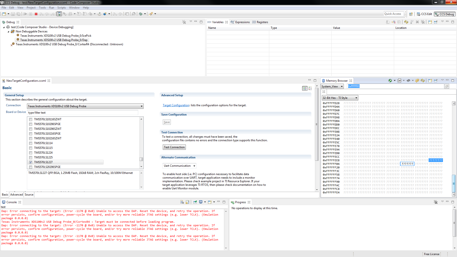
The problem shown there is pretty similar to mine so I tried to follow the sequence suggested by the TI employee and I got stuck in the step 5 (I cannot connect the DAP). If I try (as suggested a couple post later) to reset the device before going to the next step it allows me to connect de DAP but when I open the memory browser, the highest memory address that I can acces is 0xFFFFFFE4 so I cannot go forward to the next step. Also, all the memory adressess are shown as ???????? so I could not change the value even I I had access to it. Moreover once I reach this point the program (CCS6) always crashes and I have to restart it. I have attached an image of the screen at that moment.
I also want to point out that the problem encountered is program independent in the sense that it happens no matter what project you try to load.
I have also tested power supply voltages and clocks of the different chips in the controlboard to check if everything was ok and I did not find any problem at all.
Is there any way to recover the controlcard?
Best regards,
Javier Vara

