This thread has been locked.

If you have a related question, please click the "Ask a related question" button in the top right corner. The newly created question will be automatically linked to this question.

Kentec Boosterpack with TM4C123 launchpad not working

Other Parts Discussed in Thread: BOOSTXL-K350QVG-S1, EK-TM4C123GXL, EK-TM4C1294XL, TM4C123GH6PM, LMFLASHPROGRAMMER

Hello, 

I've recently order a Kentec boosterpack, and I've extensively tried to make it work on the TM4C123 launchpad, but I'm convinced the order came with a faulty display. I've tried loading it using various drivers and projects that seem to work for other people. For example:

  • Keil project seen on the .zip file "Kentec_4C123.zip" on Valvano's website
  • njneers "freq-analyzer project" which i found on github
  • Texas Instruments lab 10, found on the lab workbook. (To which I've used the sample codes)

My display is set up correctly, with the kentec label close to the two launchpad buttons. I've also tried removing it just a bit from the pins so the power and ground from the launchpad don't touch the connector strip.

After (succesfully) building, running and debugging all three of these codes, the kentec display does not show any sign of life whatsoever on all three of them, leading me to believe I have a malfunctioning device. 

I'd like to know what test I can still try on the display to confirm it's not working. 

Thanks, Paulo

  • Hello Paulo,

    Can you connect a LA or Scope to the communication pins between the display and the launchpad and see if any response is returned by the panel during the setup?

    Regards
    Amit
  • Beyond L.A./Scope - have you measured to insure that the proper voltage levels reach your display?

    Your report, "not working" may not provide sufficient descriptive detail to best enable your remote (i.e. blind) helpers. Does the backlight come on. Some, many, few pixels? Is the image stable?

    Is there some chance you misconnected the display - however briefly?   Your, "conviction" that the display is faulty - and that it "came in that way" - may arouse suspicion...

    Suggest that - when you return the display/product - avoid mentioning (both) your DOA "conviction" & the "Display removal to avoid contacting connecting strips!"     That's hugely "coincidental" is it not?

    As past display vendor - its rare for such displays to arrive "bad."    Facts you present here suggest that "improper handling" proved a most likely culprit...

  • Hello Amit,

    I will have access to a scope on monday. I will check on that and get back to you.

    Thanks, 

    Paulo

  • Hello cb1-,

    Nothing whatsoever happens when I connect it. I'm usually very careful about connecting hardware, I triple check everything, especially ones that I pay $25 for. Of course, I will not negate the possibility that "some" haywire connection could have gone awry without my noticing, but I find that unlikely.

    I am not convinced the display is faulty, it could still be some sort of Software incompatibility. I'll make sure of that first by checking it with a scope, and if it shows no return signals, then I'll conclude that the display either came faulty, or I messed it up in some way that escapes me.

    Paulo

  • Hi Paulo,

    I'm on your side - but unless the backlight is SW controlled - it should illuminate w/power up.

    May be that I'm among few here trained both Eng & Law - advice I offered was to assist you in a "successful" return. (as your writing stood - it raised "user-handling" questions)

    Your report, "tried removing it just a bit from the pins - so the power and ground from the launchpad don't touch the connector strip" strongly signals a, "User handling issue." You may wish to "avoid" that statement while seeking a replacement - should such need arise

    We - and perhaps your Lcd too - remain, "in the dark" as to the presence of any pixels and backlight - which at minimum signal the (now) correct power polarity....
  • Hi cb1-,

    The comment I made concerning "removing the device away from pins" is actually written in the Kentec technical document provided by Texas. When you attach the Boosterpack, the connection strip is pretty much touching some pins on the launchpad. If this is what actually "fried" my device, then I would be really impressed at this design flaw. Hopefully this is not the case.

    In any case, thank you for your advice, I will definitely heed it should I apply to a return! :)

    Paulo
  • Hi Paulo,

    Ouch - sounds like, "best practice" ran a poor second to, "join these two boards ... somehow" does it not?

    Over many years in the display biz (well over 100K shipped) user, "mishandling, reverse polarity & over-voltage" - caused well beyond 80% of the returns.

    Should you continue this path - you may wish to create a board and/or "connection extender" - which insures such, "illegal connections" (however briefly) cannot occur!
  • Hello Paulo

    Any update on the check from scope? Of course cb1's point are very valid as well on a possible faulty unit if the back light does not come up either.

    Regards
    Amit
  • Hi Paulo Costa,

    The booster pack for Kentec QVGA S-1; the latest available now on TI eStore is SPI interface. And all the examples on tivaware are for old booster pack which is 8-bit parallel. Have you written new drivers on tiva MCU for SPI interface? I also checked new kentec booster pack with tiva MCU TM4C123it was not working because of driver. but when I checked with MSP432 launchpad the kentec booster pack is working fine. Since the MSP432 driver example is in SPI interface. Please check the pin configuration and SPI drivers. Hope this will help.

    Thanks.

    Abdu Sattar Malokani
  • The example you linked above all using 8-bit parallel interface driver. So they will not work with new Kentec booster pack (which is SPI Interface). Have look at MSP432 Kentec SPI drivers and modify accordingly. thanks.

    Sattar Malokani
  • Thank you for providing such info - pity that such changes (if indeed that's this poster's case) are not well marked & properly highlighted.

    As you report a change from 8 bit parallel to SPI - might that be reflected @ the connector interface - between display & MCU board?    One would expect that such connector scheme would reduce - thus serving as a "safeguard" against an "inappropriate" match of MCU board to display.

  • TI did not Highlighted about that change from 8-bit to SPI. I was also struggling that what is wrong with Tiva TM4c123, but when I read the Lab10 tiva workshop then I found that there they are using 8-bit parallel interface, while the new booster pack (Kentec QVGA S-1) is designed with SPI interface. Other free pins they have connected to the ground so there is no way to use 8-bit interface with tiva series. only way is to write new SPI drivers.

    Thanks

  • Thank you - what a great service you've provided - most resourceful and welcome!

    When "new" replaces "old" - and is improperly marked/noted - outcome most always proves, "unpleasant."
  • Hello Sattar,

    Then the display driver code from the DK-TM4C123 panel may be used as a builder for the new SPI interface. Honestly, I am surprised by the change as well.

    Regards
    Amit
  • Hi Amit Ashara,

    Here are the drivers for the TM4C123gx launchpad. I hope these will be helpful for others also. 

    //*****************************************************************************
    //
    // Kentec320x240x16_ssd2119_SPI.c - Display driver for the Kentec
    //                                  BOOSTXL-K350QVG-S1 TFT display with an SSD2119
    //                                  controller.  This version assumes an SPI interface
    //                                  between the micro and display.
    //
    //*****************************************************************************
    
    //*****************************************************************************
    //
    //! \addtogroup display_api
    //! @{
    //
    //*****************************************************************************
    #include <stdint.h>
    #include <stdbool.h>
    #include "inc/hw_gpio.h"
    #include "inc/hw_ints.h"
    #include "inc/hw_memmap.h"
    #include "inc/hw_types.h"
    #include "driverlib/ssi.h"
    #include "driverlib/gpio.h"
    #include "driverlib/interrupt.h"
    #include "driverlib/sysctl.h"
    #include "driverlib/timer.h"
    #include "driverlib/rom.h"
    #include "driverlib/pin_map.h"
    #include "grlib/grlib.h"
    #include "drivers/Kentec320x240x16_SSD2119_SPI.h"
    //*****************************************************************************
    //
    // This driver operates in four different screen orientations.  They are:
    //
    // * Portrait - The screen is taller than it is wide, and the flex connector is
    //              on the left of the display.  This is selected by defining
    //              PORTRAIT.
    //
    // * Landscape - The screen is wider than it is tall, and the flex connector is
    //               on the bottom of the display.  This is selected by defining
    //               LANDSCAPE.
    //
    // * Portrait flip - The screen is taller than it is wide, and the flex
    //                   connector is on the right of the display.  This is
    //                   selected by defining PORTRAIT_FLIP.
    //
    // * Landscape flip - The screen is wider than it is tall, and the flex
    //                    connector is on the top of the display.  This is
    //                    selected by defining LANDSCAPE_FLIP.
    //
    // These can also be imagined in terms of screen rotation; if portrait mode is
    // 0 degrees of screen rotation, landscape is 90 degrees of counter-clockwise
    // rotation, portrait flip is 180 degrees of rotation, and landscape flip is
    // 270 degress of counter-clockwise rotation.
    //
    // If no screen orientation is selected, "landscape flip" mode will be used.
    //
    //*****************************************************************************
    #if ! defined(PORTRAIT) && ! defined(PORTRAIT_FLIP) && \
        ! defined(LANDSCAPE) && ! defined(LANDSCAPE_FLIP)
    #define LANDSCAPE
    //#define PORTRAIT_FLIP
    #endif
    
    //*****************************************************************************
    //
    // Various definitions controlling coordinate space mapping and drawing
    // direction in the four supported orientations.
    //
    //*****************************************************************************
    #ifdef PORTRAIT
    #define HORIZ_DIRECTION 0x28
    #define VERT_DIRECTION 0x20
    #define MAPPED_X(x, y) (319 - (y))
    #define MAPPED_Y(x, y) (x)
    #endif
    #ifdef LANDSCAPE
    #define HORIZ_DIRECTION 0x00
    #define VERT_DIRECTION  0x08
    #define MAPPED_X(x, y) (319 - (x))
    #define MAPPED_Y(x, y) (239 - (y))
    #endif
    #ifdef PORTRAIT_FLIP
    #define HORIZ_DIRECTION 0x18
    #define VERT_DIRECTION 0x10
    #define MAPPED_X(x, y) (y)
    #define MAPPED_Y(x, y) (239 - (x))
    #endif
    #ifdef LANDSCAPE_FLIP
    #define HORIZ_DIRECTION 0x30
    #define VERT_DIRECTION  0x38
    #define MAPPED_X(x, y) (x)
    #define MAPPED_Y(x, y) (y)
    #endif
    
    //#define SPI3	//9-bit 3-wire SPI (SSI2) mode (SCLK, SDA, SCS)
                  // Default setting for the BOOSTXL-K350QVG-S1
    							// Need to remove the "R10" (connect the "PB7/SSI2Tx" to "PD1/AIN6_TOUCH_XP") on Launchpad
    #define SPI4	//8-bit 4-wire SPI (SSI2) mode (SCLK, SDA, SCS, SDC)
    							// Need to remove the "R10" (connect the "PB7/SSI2Tx" to "PD1/AIN6_TOUCH_XP") on Launchpad
    							// Need to move the "R2" to "R3" position, 
    							// and move "R8" to "R9" position on the BOOSTXL-K350QVG-S1
    
    //*****************************************************************************
    //
    // Defines for the pins that are used to communicate with the SSD2119.
    //
    //*****************************************************************************
    #define LCD_CS_PERIPH           SYSCTL_PERIPH_GPIOA
    #define LCD_CS_BASE             GPIO_PORTA_BASE
    #define LCD_CS_PIN              GPIO_PIN_4
    
    #define LCD_DC_PERIPH           SYSCTL_PERIPH_GPIOA
    #define LCD_DC_BASE             GPIO_PORTA_BASE
    #define LCD_DC_PIN              GPIO_PIN_5
    
    #define LCD_RST_PERIPH           SYSCTL_PERIPH_GPIOD
    #define LCD_RST_BASE             GPIO_PORTD_BASE
    #define LCD_RST_PIN              GPIO_PIN_7
    
    #define LCD_LED_PERIPH           SYSCTL_PERIPH_GPIOF
    #define LCD_LED_BASE             GPIO_PORTF_BASE
    #define LCD_LED_PIN              GPIO_PIN_2
    
    //*****************************************************************************
    //
    // The dimensions of the LCD panel.
    //
    //*****************************************************************************
    #define LCD_VERTICAL_MAX 240
    #define LCD_HORIZONTAL_MAX 320
    
    #define SSD2119_ENTRY_MODE_REG        0x11
    #define SSD2119_RAM_DATA_REG          0x22
    #define SSD2119_V_RAM_POS_REG         0x44
    #define SSD2119_H_RAM_START_REG       0x45
    #define SSD2119_H_RAM_END_REG         0x46
    #define SSD2119_X_RAM_ADDR_REG        0x4E
    #define SSD2119_Y_RAM_ADDR_REG        0x4F
    #define ENTRY_MODE_DEFAULT 0x6830
    #define MAKE_ENTRY_MODE(x) ((ENTRY_MODE_DEFAULT & 0xFF00) | (x))
    
    //*****************************************************************************
    //
    // Translates a 24-bit RGB color to a display driver-specific color.
    //
    // \param c is the 24-bit RGB color.  The least-significant byte is the blue
    // channel, the next byte is the green channel, and the third byte is the red
    // channel.
    //
    // This macro translates a 24-bit RGB color into a value that can be written
    // into the display's frame buffer in order to reproduce that color, or the
    // closest possible approximation of that color.
    //
    // \return Returns the display-driver specific color.
    //
    //*****************************************************************************
    #define DPYCOLORTRANSLATE(c)    ((((c) & 0x00f80000) >> 8) |               \
                                     (((c) & 0x0000fc00) >> 5) |               \
                                     (((c) & 0x000000f8) >> 3))
    //*****************************************************************************
    //
    // Macro used to set the LCD data bus in preparation for writing a byte to the
    // device.
    //
    //*****************************************************************************
    uint16_t pui16Data[2];
    
    #ifdef SPI3
    //*****************************************************************************
    // Writes a data word to the SSD2119.  This function implements the 3-wire SPI
    // interface to the LCD display.
    //*****************************************************************************
    static void
    WriteDataSPI(unsigned short usData)
    {
    		pui16Data[0] = 0x100 | (usData >> 8);// set the most significant byte of the data.
    		pui16Data[1] = 0x100 | usData;// set the least significant byte of the data.
    
    		HWREG(LCD_CS_BASE + GPIO_O_DATA + (LCD_CS_PIN << 2)) = 0;//CS="0"
    
    		SSIDataPut(SSI2_BASE, pui16Data[0]);
    		SSIDataPut(SSI2_BASE, pui16Data[1]);
    		while(SSIBusy(SSI2_BASE)){ }   // Wait until SSI0 is done transferring all the data in the transmit FIFO.
    
    		HWREG(LCD_CS_BASE + GPIO_O_DATA + (LCD_CS_PIN << 2)) = LCD_CS_PIN;
    }
    //*****************************************************************************
    // Writes register word to the SSD2119.  This function implements the 3-wire SPI
    // interface to the LCD display.
    //*****************************************************************************
    static void
    WriteCommandSPI(unsigned short usData)
    {
    		pui16Data[0] = 0;// set the most significant byte of the data.
        pui16Data[1] = 0xFF & usData;// set the least significant byte of the data.
    
    		HWREG(LCD_CS_BASE + GPIO_O_DATA + (LCD_CS_PIN << 2)) = 0;//CS="0"
    
    		SSIDataPut(SSI2_BASE, pui16Data[0]);
    		SSIDataPut(SSI2_BASE, pui16Data[1]);
    		while(SSIBusy(SSI2_BASE)){ }   // Wait until SSI0 is done transferring all the data in the transmit FIFO.
    
    		HWREG(LCD_CS_BASE + GPIO_O_DATA + (LCD_CS_PIN << 2)) = LCD_CS_PIN;
    }
    #endif
    
    #ifdef SPI4
    //*****************************************************************************
    // Writes a data word to the SSD2119.  This function implements the 4-wire SPI
    // interface to the LCD display.
    //*****************************************************************************
    static void
    WriteDataSPI(unsigned short usData)
    {
    	pui16Data[0] = (usData >> 8);// Write the most significant byte of the data to the bus.
    	pui16Data[1] = usData;// Write the least significant byte of the data to the bus.
    
    	HWREG(LCD_DC_BASE + GPIO_O_DATA + (LCD_DC_PIN << 2)) = LCD_DC_PIN;//DC="1"
    	HWREG(LCD_CS_BASE + GPIO_O_DATA + (LCD_CS_PIN << 2)) = 0;//CS="0"
    		
    	SSIDataPut(SSI2_BASE, pui16Data[0]);
    	SSIDataPut(SSI2_BASE, pui16Data[1]);
    	while(SSIBusy(SSI2_BASE)){ }   // Wait until SSI0 is done transferring all the data in the transmit FIFO.
    
    	HWREG(LCD_CS_BASE + GPIO_O_DATA + (LCD_CS_PIN << 2)) = LCD_CS_PIN;
    }
    //*****************************************************************************
    // Writes register word to the SSD2119.  This function implements the 3-wire SPI
    // interface to the LCD display.
    //*****************************************************************************
    static void
    WriteCommandSPI(unsigned short usData)
    {
    	pui16Data[0] = 0;// Write the most significant byte of the data to the bus.
    	pui16Data[1] = usData;// Write the least significant byte of the data to the bus.
    
    	HWREG(LCD_DC_BASE + GPIO_O_DATA + (LCD_DC_PIN << 2)) = 0;//DC="0"
    	HWREG(LCD_CS_BASE + GPIO_O_DATA + (LCD_CS_PIN << 2)) = 0;//CS="0"
    	
    	SSIDataPut(SSI2_BASE, pui16Data[0]);
    	SSIDataPut(SSI2_BASE, pui16Data[1]);
    	while(SSIBusy(SSI2_BASE)){ }   // Wait until SSI0 is done transferring all the data in the transmit FIFO.
    
    	HWREG(LCD_CS_BASE + GPIO_O_DATA + (LCD_CS_PIN << 2)) = LCD_CS_PIN;
    }
    #endif
    
    //*****************************************************************************
    // Initializes the LCD interface.
    // Enable the SSI2 for LCD data/register transfer.
    // Set the LCD_CS_PIN, LCD_DC_PIN, LCD_RST_PIN.
    //*****************************************************************************
    static void
    LCD_PORT_Init(void)
    {		
    		uint32_t pui32DataRx[3];
    		
        // The SSI2 peripheral must be enabled for use.
    		SysCtlPeripheralEnable(SYSCTL_PERIPH_SSI2);
    
        // For this example SSI2 is used with PortB[7:4].  The actual port and pins
        // used may be different on your part, consult the data sheet for more
        // information.  GPIO port B needs to be enabled so these pins can be used.
        // TODO: change this to whichever GPIO port you are using.
    		SysCtlPeripheralEnable(SYSCTL_PERIPH_GPIOB);
    		
    		// Enable the PortA[5:4] for the LCD_SCS, LCD_SDC
    		// Enable the PortD[7] for LCD_RST
    		// Enable the PortF[2] for LED backlight
    		SysCtlPeripheralEnable(SYSCTL_PERIPH_GPIOA);
    		SysCtlPeripheralEnable(SYSCTL_PERIPH_GPIOD);
    		SysCtlPeripheralEnable(SYSCTL_PERIPH_GPIOF);
    
    		// Change PD7 into GPIO output.
        HWREG(GPIO_PORTD_BASE + GPIO_O_LOCK) |= GPIO_LOCK_KEY;
    		HWREG(GPIO_PORTD_BASE + GPIO_O_CR) |= 0x80;
        HWREG(GPIO_PORTD_BASE + GPIO_O_AFSEL) &= 0x7f;
    		GPIOPinTypeGPIOOutput(LCD_RST_BASE, LCD_RST_PIN);
    		
    		GPIOPinTypeGPIOOutput(LCD_CS_BASE, LCD_CS_PIN);
    		GPIOPinTypeGPIOOutput(LCD_DC_BASE, LCD_DC_PIN);
    
    		GPIOPinTypeGPIOOutput(LCD_LED_BASE, LCD_LED_PIN);
        //GPIOPadConfigSet(LCD_LED_BASE, LCD_LED_PIN, GPIO_STRENGTH_8MA, GPIO_PIN_TYPE_STD);
    
    
    		// Configure the pin muxing for SSI2 functions on port B4, B5, B6, and B7.
        // This step is not necessary if your part does not support pin muxing.
        // TODO: change this to select the port/pin you are using.
        GPIOPinConfigure(GPIO_PB4_SSI2CLK);
        GPIOPinConfigure(GPIO_PB5_SSI2FSS);
        GPIOPinConfigure(GPIO_PB6_SSI2RX);
        GPIOPinConfigure(GPIO_PB7_SSI2TX);
    		
        // Configure the GPIO settings for the SSI pins.  This function also gives
        // control of these pins to the SSI hardware.  Consult the data sheet to
        // see which functions are allocated per pin.
        // The pins are assigned as follows:
        //      PB7 - SSI2Tx
        //      PB6 - SSI2Rx
        //      PB5 - SSI2Fss
        //      PB4 - SSI2CLK
        // TODO: change this to select the port/pin you are using.
        GPIOPinTypeSSI(GPIO_PORTB_BASE, GPIO_PIN_7 | GPIO_PIN_6 | GPIO_PIN_5 | GPIO_PIN_4);
        GPIOPadConfigSet(GPIO_PORTB_BASE, GPIO_PIN_7, GPIO_STRENGTH_8MA, GPIO_PIN_TYPE_STD);
    
        // Configure and enable the SSI port for SPI master mode.  Use SSI0,
        // system clock supply, idle clock level low and active low clock in
        // freescale SPI mode, master mode, 1MHz SSI frequency, and 8-bit data.
        // For SPI mode, you can set the polarity of the SSI clock when the SSI
        // unit is idle.  You can also configure what clock edge you want to
        // capture data on.  Please reference the datasheet for more information on
        // the different SPI modes.
    	#ifdef SPI3		
    		SSIConfigSetExpClk(SSI2_BASE, SysCtlClockGet(), SSI_FRF_MOTO_MODE_0, SSI_MODE_MASTER, 20000000, 9);
    	#endif
    	#ifdef SPI4
    		SSIConfigSetExpClk(SSI2_BASE, SysCtlClockGet(), SSI_FRF_MOTO_MODE_0, SSI_MODE_MASTER, 20000000, 8);
    	#endif
        
        // Enable the SSI2 module.
        SSIEnable(SSI2_BASE);
    		
        // Read any residual data from the SSI port.  This makes sure the receive
        // FIFOs are empty, so we don't read any unwanted junk.  This is done here
        // because the SPI SSI mode is full-duplex, which allows you to send and
        // receive at the same time.  The SSIDataGetNonBlocking function returns
        // "true" when data was returned, and "false" when no data was returned.
        // The "non-blocking" function checks if there is any data in the receive
        // FIFO and does not "hang" if there isn't.
    		while(SSIDataGetNonBlocking(SSI2_BASE, &pui32DataRx[0]))    {    }
    
    }
    
    void LED_backlight_ON(void)
    {
    	HWREG(LCD_LED_BASE + GPIO_O_DATA + (LCD_LED_PIN << 2)) = LCD_LED_PIN;
    }
    void LED_backlight_OFF(void)
    {
    	HWREG(LCD_LED_BASE + GPIO_O_DATA + (LCD_LED_PIN << 2)) = 0;
    }
    
    //*****************************************************************************
    //
    //! Initializes the display driver.
    //!
    //! This function initializes the SSD2119 display controller on the panel,
    //! preparing it to display data.
    //!
    //! \return None.
    //
    //*****************************************************************************
    void
    Kentec320x240x16_SSD2119Init(void)
    {
    		unsigned int ulClockMS, ulCount;
    
        // Get the current processor clock frequency.
        ulClockMS = SysCtlClockGet() / (3 * 1000);
    
    		// Initializes the LCD port
    		LCD_PORT_Init();
    
    		// Reset the LCD
        HWREG(LCD_RST_BASE + GPIO_O_DATA + (LCD_RST_PIN << 2)) = 0;//RST="0"
        SysCtlDelay(10 * ulClockMS);
    		HWREG(LCD_RST_BASE + GPIO_O_DATA + (LCD_RST_PIN << 2)) = LCD_RST_PIN;//RST="1"
        SysCtlDelay(20 * ulClockMS);
    
        // Enter sleep mode (if we are not already there).
        WriteCommandSPI(0x10);//SLEEP_MODE_REG
        WriteDataSPI(0x0001);
    
        //
        // Set initial power parameters.
        //
        WriteCommandSPI(0x1E);//SSD2119_PWR_CTRL_5_REG
        WriteDataSPI(0x00BA);
        WriteCommandSPI(0x28);//SSD2119_VCOM_OTP_1_REG
        WriteDataSPI(0x0006);
    
        //
        // Start the oscillator.
        //
        WriteCommandSPI(0x00);
        WriteDataSPI(0x0001);
    
        //
        // Set pixel format and basic display orientation (scanning direction).
        //
        WriteCommandSPI(0x01);
        WriteDataSPI(0x30EF);
        WriteCommandSPI(0x02);
        WriteDataSPI(0x0600);
    
        //
        // Exit sleep mode.
        //
        WriteCommandSPI(0x10);//SSD2119_SLEEP_MODE_REG
        WriteDataSPI(0x0000);
    
        //
        // Delay 30mS
        //
        SysCtlDelay(30 * ulClockMS);
    
        //
        // Configure pixel color format and MCU interface parameters.
        //
        WriteCommandSPI(SSD2119_ENTRY_MODE_REG);
        WriteDataSPI(ENTRY_MODE_DEFAULT);
    
        //
        // Enable the display.
        //
        WriteCommandSPI(0x07);
        WriteDataSPI(0x0033);
    
        //
        // Set VCIX2 voltage to 6.1V.
        //
        WriteCommandSPI(0x0C);//SSD2119_PWR_CTRL_2_REG
        WriteDataSPI(0x0005);
    
        //
        // Configure gamma correction.
        //
        WriteCommandSPI(0x30);    WriteDataSPI(0x0000);//SSD2119_GAMMA_CTRL_1
        WriteCommandSPI(0x31);    WriteDataSPI(0x0400);//SSD2119_GAMMA_CTRL_2
        WriteCommandSPI(0x32);    WriteDataSPI(0x0106);//SSD2119_GAMMA_CTRL_3
        WriteCommandSPI(0x33);    WriteDataSPI(0x0700);//SSD2119_GAMMA_CTRL_4
        WriteCommandSPI(0x34);    WriteDataSPI(0x0002);//SSD2119_GAMMA_CTRL_5
        WriteCommandSPI(0x35);    WriteDataSPI(0x0702);//SSD2119_GAMMA_CTRL_6
        WriteCommandSPI(0x36);    WriteDataSPI(0x0707);//SSD2119_GAMMA_CTRL_7
        WriteCommandSPI(0x37);    WriteDataSPI(0x0203);//SSD2119_GAMMA_CTRL_8
        WriteCommandSPI(0x3A);    WriteDataSPI(0x1400);//SSD2119_GAMMA_CTRL_9
        WriteCommandSPI(0x3B);    WriteDataSPI(0x0F03);//SSD2119_GAMMA_CTRL_10
    
        //
        // Configure Vlcd63 and VCOMl.
        //
        WriteCommandSPI(0x0D);//SSD2119_PWR_CTRL_3_REG
        WriteDataSPI(0x0007);
        WriteCommandSPI(0x0E);//SSD2119_PWR_CTRL_4_REG
        WriteDataSPI(0x3100);
    
        //
        // Set the display size and ensure that the GRAM window is set to allow
        // access to the full display buffer.
        //
        WriteCommandSPI(SSD2119_V_RAM_POS_REG);
        WriteDataSPI((LCD_VERTICAL_MAX-1) << 8);
        WriteCommandSPI(SSD2119_H_RAM_START_REG);
        WriteDataSPI(0x0000);
        WriteCommandSPI(SSD2119_H_RAM_END_REG);
        WriteDataSPI(LCD_HORIZONTAL_MAX-1);
        WriteCommandSPI(SSD2119_X_RAM_ADDR_REG);
        WriteDataSPI(0x00);
        WriteCommandSPI(SSD2119_Y_RAM_ADDR_REG);
        WriteDataSPI(0x00);
    
        // Clear the contents of the display buffer.
        WriteCommandSPI(SSD2119_RAM_DATA_REG);
        for(ulCount = 0; ulCount < (320 * 240); ulCount++)
        {
            WriteDataSPI(0x0000);
        }
    		LED_backlight_ON();
    }
    
    //*****************************************************************************
    //
    //! Draws a pixel on the screen.
    //!
    //! \param pvDisplayData is a pointer to the driver-specific data for this
    //! display driver.
    //! \param lX is the X coordinate of the pixel.
    //! \param lY is the Y coordinate of the pixel.
    //! \param ulValue is the color of the pixel.
    //!
    //! This function sets the given pixel to a particular color.  The coordinates
    //! of the pixel are assumed to be within the extents of the display.
    //!
    //! \return None.
    //
    //*****************************************************************************
    static void
    Kentec320x240x16_SSD2119PixelDraw(void *pvDisplayData, int lX, int lY,
                                       unsigned int ulValue)
    {
        //
        // Set the X address of the display cursor.
        //
        WriteCommandSPI(SSD2119_X_RAM_ADDR_REG);
        WriteDataSPI(MAPPED_X(lX, lY));
    
        //
        // Set the Y address of the display cursor.
        //
        WriteCommandSPI(SSD2119_Y_RAM_ADDR_REG);
        WriteDataSPI(MAPPED_Y(lX, lY));
    
        //
        // Write the pixel value.
        //
        WriteCommandSPI(SSD2119_RAM_DATA_REG);
        WriteDataSPI(ulValue);
    }
    
    //*****************************************************************************
    //
    //! Draws a horizontal sequence of pixels on the screen.
    //!
    //! \param pvDisplayData is a pointer to the driver-specific data for this
    //! display driver.
    //! \param lX is the X coordinate of the first pixel.
    //! \param lY is the Y coordinate of the first pixel.
    //! \param lX0 is sub-pixel offset within the pixel data, which is valid for 1
    //! or 4 bit per pixel formats.
    //! \param lCount is the number of pixels to draw.
    //! \param lBPP is the number of bits per pixel; must be 1, 4, or 8.
    //! \param pucData is a pointer to the pixel data.  For 1 and 4 bit per pixel
    //! formats, the most significant bit(s) represent the left-most pixel.
    //! \param pucPalette is a pointer to the palette used to draw the pixels.
    //!
    //! This function draws a horizontal sequence of pixels on the screen, using
    //! the supplied palette.  For 1 bit per pixel format, the palette contains
    //! pre-translated colors; for 4 and 8 bit per pixel formats, the palette
    //! contains 24-bit RGB values that must be translated before being written to
    //! the display.
    //!
    //! \return None.
    //
    //*****************************************************************************
    static void
    Kentec320x240x16_SSD2119PixelDrawMultiple(void *pvDisplayData, int lX,
                                               int lY, int lX0, int lCount,
                                               int lBPP,
                                               const unsigned char *pucData,
                                               const unsigned char *pucPalette)
    {
        unsigned int ulByte;
    
        //
        // Set the cursor increment to left to right, followed by top to bottom.
        //
        WriteCommandSPI(SSD2119_ENTRY_MODE_REG);
        WriteDataSPI(MAKE_ENTRY_MODE(HORIZ_DIRECTION));
    
        //
        // Set the starting X address of the display cursor.
        //
        WriteCommandSPI(SSD2119_X_RAM_ADDR_REG);
        WriteDataSPI(MAPPED_X(lX, lY));
    
        //
        // Set the Y address of the display cursor.
        //
        WriteCommandSPI(SSD2119_Y_RAM_ADDR_REG);
        WriteDataSPI(MAPPED_Y(lX, lY));
    
        //
        // Write the data RAM write command.
        //
        WriteCommandSPI(SSD2119_RAM_DATA_REG);
    
        //
        // Determine how to interpret the pixel data based on the number of bits
        // per pixel.
        //
        switch(lBPP)
        {
            //
            // The pixel data is in 1 bit per pixel format.
            //
            case 1:
            {
                //
                // Loop while there are more pixels to draw.
                //
                while(lCount)
                {
                    //
                    // Get the next byte of image data.
                    //
                    ulByte = *pucData++;
    
                    //
                    // Loop through the pixels in this byte of image data.
                    //
                    for(; (lX0 < 8) && lCount; lX0++, lCount--)
                    {
                        //
                        // Draw this pixel in the appropriate color.
                        //
                        WriteDataSPI(((unsigned int *)pucPalette)[(ulByte >>
                                                                 (7 - lX0)) & 1]);
                    }
    
                    //
                    // Start at the beginning of the next byte of image data.
                    //
                    lX0 = 0;
                }
    
                //
                // The image data has been drawn.
                //
                break;
            }
    
            //
            // The pixel data is in 4 bit per pixel format.
            //
            case 4:
            {
                //
                // Loop while there are more pixels to draw.  "Duff's device" is
                // used to jump into the middle of the loop if the first nibble of
                // the pixel data should not be used.  Duff's device makes use of
                // the fact that a case statement is legal anywhere within a
                // sub-block of a switch statement.  See
                // http://en.wikipedia.org/wiki/Duff's_device for detailed
                // information about Duff's device.
                //
                switch(lX0 & 1)
                {
                    case 0:
                        while(lCount)
                        {
                            //
                            // Get the upper nibble of the next byte of pixel data
                            // and extract the corresponding entry from the
                            // palette.
                            //
                            ulByte = (*pucData >> 4) * 3;
                            ulByte = (*(unsigned int *)(pucPalette + ulByte) &
                                      0x00ffffff);
    
                            //
                            // Translate this palette entry and write it to the
                            // screen.
                            //
                            WriteDataSPI(DPYCOLORTRANSLATE(ulByte));
    
                            //
                            // Decrement the count of pixels to draw.
                            //
                            lCount--;
    
                            //
                            // See if there is another pixel to draw.
                            //
                            if(lCount)
                            {
                    case 1:
                                //
                                // Get the lower nibble of the next byte of pixel
                                // data and extract the corresponding entry from
                                // the palette.
                                //
                                ulByte = (*pucData++ & 15) * 3;
                                ulByte = (*(unsigned int *)(pucPalette + ulByte) &
                                          0x00ffffff);
    
                                //
                                // Translate this palette entry and write it to the
                                // screen.
                                //
                                WriteDataSPI(DPYCOLORTRANSLATE(ulByte));
    
                                //
                                // Decrement the count of pixels to draw.
                                //
                                lCount--;
                            }
                        }
                }
    
                //
                // The image data has been drawn.
                //
                break;
            }
    
            //
            // The pixel data is in 8 bit per pixel format.
            //
            case 8:
            {
                //
                // Loop while there are more pixels to draw.
                //
                while(lCount--)
                {
                    //
                    // Get the next byte of pixel data and extract the
                    // corresponding entry from the palette.
                    //
                    ulByte = *pucData++ * 3;
                    ulByte = *(unsigned int *)(pucPalette + ulByte) & 0x00ffffff;
    
                    //
                    // Translate this palette entry and write it to the screen.
                    //
                    WriteDataSPI(DPYCOLORTRANSLATE(ulByte));
                }
    
                //
                // The image data has been drawn.
                //
                break;
            }
    
            //
            // We are being passed data in the display's native format.  Merely
            // write it directly to the display.  This is a special case which is
            // not used by the graphics library but which is helpful to
            // applications which may want to handle, for example, JPEG images.
            //
            case 16:
            {
                unsigned short usByte;
    
                //
                // Loop while there are more pixels to draw.
                //
                while(lCount--)
                {
                    //
                    // Get the next byte of pixel data and extract the
                    // corresponding entry from the palette.
                    //
                    usByte = *((unsigned short *)pucData);
                    pucData += 2;
    
                    //
                    // Translate this palette entry and write it to the screen.
                    //
                    WriteDataSPI(usByte);
                }
            }
        }
    }
    
    //*****************************************************************************
    //
    //! Draws a horizontal line.
    //!
    //! \param pvDisplayData is a pointer to the driver-specific data for this
    //! display driver.
    //! \param lX1 is the X coordinate of the start of the line.
    //! \param lX2 is the X coordinate of the end of the line.
    //! \param lY is the Y coordinate of the line.
    //! \param ulValue is the color of the line.
    //!
    //! This function draws a horizontal line on the display.  The coordinates of
    //! the line are assumed to be within the extents of the display.
    //!
    //! \return None.
    //
    //*****************************************************************************
    static void
    Kentec320x240x16_SSD2119LineDrawH(void *pvDisplayData, int lX1, int lX2,
                                       int lY, unsigned int ulValue)
    {
        //
        // Set the cursor increment to left to right, followed by top to bottom.
        //
        WriteCommandSPI(SSD2119_ENTRY_MODE_REG);
        WriteDataSPI(MAKE_ENTRY_MODE(HORIZ_DIRECTION));
    
        //
        // Set the starting X address of the display cursor.
        //
        WriteCommandSPI(SSD2119_X_RAM_ADDR_REG);
        WriteDataSPI(MAPPED_X(lX1, lY));
    
        //
        // Set the Y address of the display cursor.
        //
        WriteCommandSPI(SSD2119_Y_RAM_ADDR_REG);
        WriteDataSPI(MAPPED_Y(lX1, lY));
    
        //
        // Write the data RAM write command.
        //
        WriteCommandSPI(SSD2119_RAM_DATA_REG);
    
        //
        // Loop through the pixels of this horizontal line.
        //
        while(lX1++ <= lX2)
        {
            //
            // Write the pixel value.
            //
            WriteDataSPI(ulValue);
        }
    }
    
    //*****************************************************************************
    //
    //! Draws a vertical line.
    //!
    //! \param pvDisplayData is a pointer to the driver-specific data for this
    //! display driver.
    //! \param lX is the X coordinate of the line.
    //! \param lY1 is the Y coordinate of the start of the line.
    //! \param lY2 is the Y coordinate of the end of the line.
    //! \param ulValue is the color of the line.
    //!
    //! This function draws a vertical line on the display.  The coordinates of the
    //! line are assumed to be within the extents of the display.
    //!
    //! \return None.
    //
    //*****************************************************************************
    static void
    Kentec320x240x16_SSD2119LineDrawV(void *pvDisplayData, int lX, int lY1,
                                       int lY2, unsigned int ulValue)
    {
        //
        // Set the cursor increment to top to bottom, followed by left to right.
        //
        WriteCommandSPI(SSD2119_ENTRY_MODE_REG);
        WriteDataSPI(MAKE_ENTRY_MODE(VERT_DIRECTION));
    
        //
        // Set the X address of the display cursor.
        //
        WriteCommandSPI(SSD2119_X_RAM_ADDR_REG);
        WriteDataSPI(MAPPED_X(lX, lY1));
    
        //
        // Set the starting Y address of the display cursor.
        //
        WriteCommandSPI(SSD2119_Y_RAM_ADDR_REG);
        WriteDataSPI(MAPPED_Y(lX, lY1));
    
        //
        // Write the data RAM write command.
        //
        WriteCommandSPI(SSD2119_RAM_DATA_REG);
    
        //
        // Loop through the pixels of this vertical line.
        //
        while(lY1++ <= lY2)
        {
            //
            // Write the pixel value.
            //
            WriteDataSPI(ulValue);
        }
    }
    
    //*****************************************************************************
    //
    //! Fills a rectangle.
    //!
    //! \param pvDisplayData is a pointer to the driver-specific data for this
    //! display driver.
    //! \param pRect is a pointer to the structure describing the rectangle.
    //! \param ulValue is the color of the rectangle.
    //!
    //! This function fills a rectangle on the display.  The coordinates of the
    //! rectangle are assumed to be within the extents of the display, and the
    //! rectangle specification is fully inclusive (in other words, both sXMin and
    //! sXMax are drawn, along with sYMin and sYMax).
    //!
    //! \return None.
    //
    //*****************************************************************************
    static void
    Kentec320x240x16_SSD2119RectFill(void *pvDisplayData, const tRectangle *pRect,
                                      unsigned int ulValue)
    {
        int lCount;
    
        //
        // Write the Y extents of the rectangle.
        //
        WriteCommandSPI(SSD2119_ENTRY_MODE_REG);
        WriteDataSPI(MAKE_ENTRY_MODE(HORIZ_DIRECTION));
    
        //
        // Write the X extents of the rectangle.
        //
        WriteCommandSPI(SSD2119_H_RAM_START_REG);
    #if (defined PORTRAIT) || (defined LANDSCAPE)
        WriteDataSPI(MAPPED_X(pRect->i16XMax, pRect->i16YMax));
    #else
        WriteDataSPI(MAPPED_X(pRect->i16XMin, pRect->i16YMin));
    #endif
    
        WriteCommandSPI(SSD2119_H_RAM_END_REG);
    #if (defined PORTRAIT) || (defined LANDSCAPE)
        WriteDataSPI(MAPPED_X(pRect->i16XMin, pRect->i16YMin));
    #else
        WriteDataSPI(MAPPED_X(pRect->i16XMax, pRect->i16YMax));
    #endif
    
        //
        // Write the Y extents of the rectangle
        //
        WriteCommandSPI(SSD2119_V_RAM_POS_REG);
    #if (defined LANDSCAPE_FLIP) || (defined PORTRAIT)
        WriteDataSPI(MAPPED_Y(pRect->i16XMin, pRect->i16YMin) |
                 (MAPPED_Y(pRect->i16XMax, pRect->i16YMax) << 8));
    #else
        WriteDataSPI(MAPPED_Y(pRect->i16XMax, pRect->i16YMax) |
                 (MAPPED_Y(pRect->i16XMin, pRect->i16YMin) << 8));
    #endif
    
        //
        // Set the display cursor to the upper left of the rectangle (in application
        // coordinate space).
        //
        WriteCommandSPI(SSD2119_X_RAM_ADDR_REG);
        WriteDataSPI(MAPPED_X(pRect->i16XMin, pRect->i16YMin));
    
        WriteCommandSPI(SSD2119_Y_RAM_ADDR_REG);
        WriteDataSPI(MAPPED_Y(pRect->i16XMin, pRect->i16YMin));
    
        //
        // Tell the controller we are about to write data into its RAM.
        //
        WriteCommandSPI(SSD2119_RAM_DATA_REG);
    
        //
        // Loop through the pixels of this filled rectangle.
        //
        for(lCount = ((pRect->i16XMax - pRect->i16XMin + 1) *
                      (pRect->i16YMax - pRect->i16YMin + 1)); lCount >= 0; lCount--)
        {
            //
            // Write the pixel value.
            //
            WriteDataSPI(ulValue);
        }
    
        //
        // Reset the X extents to the entire screen.
        //
        WriteCommandSPI(SSD2119_H_RAM_START_REG);
        WriteDataSPI(0x0000);
        WriteCommandSPI(SSD2119_H_RAM_END_REG);
        WriteDataSPI(0x013F);
    
        //
        // Reset the Y extent to the full screen
        //
        WriteCommandSPI(SSD2119_V_RAM_POS_REG);
        WriteDataSPI(0xEF00);
    }
    
    //*****************************************************************************
    //
    //! Translates a 24-bit RGB color to a display driver-specific color.
    //!
    //! \param pvDisplayData is a pointer to the driver-specific data for this
    //! display driver.
    //! \param ulValue is the 24-bit RGB color.  The least-significant byte is the
    //! blue channel, the next byte is the green channel, and the third byte is the
    //! red channel.
    //!
    //! This function translates a 24-bit RGB color into a value that can be
    //! written into the display's frame buffer in order to reproduce that color,
    //! or the closest possible approximation of that color.
    //!
    //! \return Returns the display-driver specific color.
    //
    //*****************************************************************************
    static unsigned int
    Kentec320x240x16_SSD2119ColorTranslate(void *pvDisplayData,
                                            unsigned int ulValue)
    {
        //
        // Translate from a 24-bit RGB color to a 5-6-5 RGB color.
        //
        return(DPYCOLORTRANSLATE(ulValue));
    }
    
    //*****************************************************************************
    //
    //! Flushes any cached drawing operations.
    //!
    //! \param pvDisplayData is a pointer to the driver-specific data for this
    //! display driver.
    //!
    //! This functions flushes any cached drawing operations to the display.  This
    //! is useful when a local frame buffer is used for drawing operations, and the
    //! flush would copy the local frame buffer to the display.  For the SSD2119
    //! driver, the flush is a no operation.
    //!
    //! \return None.
    //
    //*****************************************************************************
    static void
    Kentec320x240x16_SSD2119Flush(void *pvDisplayData)
    {
        //
        // There is nothing to be done.
        //
    }
    //*****************************************************************************
    //
    //! The display structure that describes the driver for the Kentec
    //! K350QVG-V2-F TFT panel with an SSD2119 controller.
    //
    //*****************************************************************************
    const tDisplay g_sKentec320x240x16_SSD2119 =
    {
        sizeof(tDisplay),
        0,
    #if defined(PORTRAIT) || defined(PORTRAIT_FLIP)
        240,
        320,
    #else
        320,
        240,
    #endif
        Kentec320x240x16_SSD2119PixelDraw,
        Kentec320x240x16_SSD2119PixelDrawMultiple,
        Kentec320x240x16_SSD2119LineDrawH,
        Kentec320x240x16_SSD2119LineDrawV,
        Kentec320x240x16_SSD2119RectFill,
        Kentec320x240x16_SSD2119ColorTranslate,
        Kentec320x240x16_SSD2119Flush
    };
    
    //*****************************************************************************
    //
    // Close the Doxygen group.
    //! @}
    //
    //*****************************************************************************
    
    Kentec320x240x16_SSD2119_SPI.h 

  • Hi Amit,

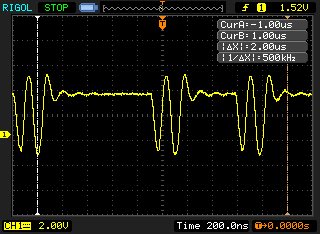
    I spent some time trying to figure out how to capture a signal from the osciloscope I have access to (Rigol DS1052), but there's not digital analyzer in it, so I just got Analog readings from a few pins.

    I wasn't sure where to look, so I looked at PA5 (Write control signal) , PA6 (Register/Data select signal) and PE4 (X+ on the boosterpack).

    This is PA6:

    This is PA5 (this is a very weird signal to me):

    And PE4 shows nothing (which is supposedly an input).

    Also, the backlight is not turned on when I connect the USB. Are there any tests you may suggest that can be more informative (I don't think these bmps tell us anything).

    Thanks, 

    Paulo

  • Hi Sattar,

    Thank you so much for these! I will test them out and see if they work. Also, do you have any comment on the backlight issue? Does it need to be activated in software or does it come up as soon as the USB is plugged in?

    Thanks,
    Paulo
  • Hi Sattar, Amit and cb1-,

    When I substituted the drivers Sattar posted, and ran the Lab10 code, the display lit up!
    The program doesn't work still, nothing shows up except the backlight, so there's still a ton I have to investigate. At least I know it's functioning, and now feel comfortable to properly look into how the drivers work.

    Hopefully someone can update the page, I feel this change is rather important and that the proper drivers need to be made available.

    Thanks,
    Paulo
  • Paulo Costa said:
    does it (the display's backlight) come up as soon as the USB is plugged in?   

    It remains unexpected and confounding that both this MCU vendor & display vendor - could produce 2 different display sub-systems - which would "share" a common MCU connection header - yet "attach" via entirely different interfaces!     I find this highly unusual - and must suspect that (somewhere) there is a necessary (yet still missing) "link" - which properly describes & clarifies.

    And just today arrives (from Paulo) the news that (apparently) this multi-board (barely described) "system" is powered via a USB cable!     Are not these (usually) limited to 500mA - and can the L-Pad, and the Display (to include its backlight) remain w/in this 500mA, USB, current limit?

    It's unknown if the display - which Sattar has and describes - is indeed the same one used by Paulo.     Are not there part numbers on these - and should not these be presented here - and thus compared?     And there are different "flavors" of L-Pads too - isn't that true?     Does Paulo's display and L-Pad (really) match Sattar's - at this stage I cannot tell.

    Something seems not (quite right) and an email or call to the Lcd Vendor seems most necessary - along with a full listing of, "just what's in play" (both @ Paulo & @ Sattar) - to properly contrast & resolve.     If a camera proves handy - at both ends - such may speed & ease the comparison.     (any display identifying numbers or connectors would prove of interest)

    Change is usual - to be expected - but a change of this magnitude - (apparently) unannounced - is (far) outside the "norm."

    [edit  16:55 CST] - Paulo - our posts just crossed - much explained by your writing.    I'd suggest that your first order of business is to find and then insure that all connections between your MCU board and the Display are to specification.      You must guard against illegal introduction of voltage and/or against connecting 2 outputs together!     There must be a (recent) written spec - I'd remove all power till that's present - and you've made a detailed check...

  • Hi cb1-, thanks for your feedback.
    I've double checked the connections, and these are the pins for the boosterpack that I matched using the Datasheet.

    ==========================================
    Pin Name ------------ TM4C123 Pin Name

    PWM ------------------ PF2
    LCD_SDI -------------PB7(MOSI(2))
    LCD_SCS ------------PA4(MISO(0))
    Y- -----------------------PA2(SCK(0))
    X- -----------------------PF4
    LCD_RESET --------PD7

    Y+ ----------------------PD0(SCK(3))
    X+ ----------------------PD1(CAS(3))
    LCD_SCL ------------PB4(SCK(2))
    LCD_SDC ----------- PA5(MOSI(0))
    ==========================================

    It seems to be in line with the comment on Sattar's driver:

    / For this example SSI2 is used with PortB[7:4]. The actual port and pins
    // used may be different on your part, consult the data sheet for more
    // information. GPIO port B needs to be enabled so these pins can be used.
    // TODO: change this to whichever GPIO port you are using.

    Except that there PB5 and PB6 are not connected to anything, as it seems. Not sure if herein lies the problem, but since the "lcd_backlight_ON();" command works, I'm assuming this is correct.

    Anyways, I really need some sort of working code so I can learn how to use the graphics library. The Lab10 code does not work, and I don't know how to debug it.. I can't tell if it's the driver or the GRL usage, and I really don't want to go too much into the SSD2119 datasheet... If any of you could help me getting this up and running, that would be fantastic!

    I've never had this much trouble getting a display to work.

    Thanks,
    Paulo

  • As stated - an email to Lcd vendor - (gently) describing your struggles - and requesting clarification (and code) - should work wonders...
  • Hi Paulo Costa,

    That is great at least your booster pack back light is working. Theses drivers are working fine with TM4C123gxl, and only touch is not working because of pin configurations i need to check this. In Tiva workshop lab10 folder you will find three main files named as main1.txt, main2.txt and mani3.txt. So copy any of these code and try.

    In lab10 folder there is also grlib_demo.c and MyWidget.txt files. These both files are using touch, If you comment TouchScreenInit() then these both will start working but without touch.  The back light is not turned on when you plug the booster pack, it is through software.   I hope this will solve your problem.

    Regards,

    Sattar Malokani

  • Hi Sattar,

    Your suggestions did not work, the only thing that is turned on is the display light. I sent Kentec an email, as suggested by cb1-, and they sent me some example projects as well, and all had the same problem. Upon my reply, the technician said to "make sure I remove R10 from the launchpad". R10 is an SMD resistor.

    Does your Launchpad still have that resistor? I really don't want to remove components from my launchpad for this to work. Also, I'm using CCS, not sure if that can be the problem.

    Thanks,
    Paulo
  • Hi Paulo,

    I have a couple of them together with MSP432 Launchpad coming with a running demo available from:

    C:\ti\msp430\MSPWare_2_10_00_15\examples\boards\MSP-EXP432P401R\MSP-EXP432P401R Software Examples\Source\BOOSTXL-K350QVG-S1_GrlibExample_MSP432P401R

    or from CCS resource explore.

    Maybe getting MSP432 Launchpad will save you some time in porting drivers to Tiva

    Hope this will help.

    Jan

  • But to my launchpad is working fine. Yes I removed R10 resistor.  Just remove resistor and try. It is working fine on my launchpad but without touch.

    Regards

    Sattar malokani

  • Hi Jan,

    I have also MSP432 launchpad and kentec booster pack. But when i connected the booster pack to MSP432 two parts on debug side regulator chip and usb chip getting too hot. Is it the case with you would you please let me know.? Thanks

    Sattar Malokani
  • Hi Sattar,

    No such a problem on my 2 boards.

    Are you able to successfully load and run a demo software?

    Can you try without LCD? Try loading demo software with booster pack disconnected.

    I have initially a problem with one board having a blank display and needed to unplag and plag again it (the LCD booster pack) carefully and it start working.

    The demo has always a problem with touch calibration.

    Jan

  • Hi Jan,

    Thank you for your quick reply. I have carefully checked my MSP432 launchpad, and I see that it has internally became short. The VCC and Ground pins are short. I checked that two capacitors 2.2uf (do not remember the exact number) were short and they make trouble to other components also. But I have also TM4C123gx which is working fine.

    Thanks.

    Sattar Malokani
  • Let the record show that Tiva L-Pads long have employed 0Ω smt resistors (R9 & R10) to "maintain compatibility" w/past MSP boards - YET those resistors directly short circuit MCU pins!

    I've long argued that far, far fewer users are "helped" - rather than "hurt" - by the inclusion of these "dead short, MCU pin to pin" resistors.
  • Hi SATTAR MALOKANI,

    I also working with "grlib_demo" project using Kentec Displays BOOSTXL-K350QVG-S1 connected to a EK-TM4C123GXL Launchpad, the LCD displays correctly but only touch not woking. I don't know why touch isn't work with my EK-TM4C123GXL Launchpad?. There is have a error with "grlib_demo" project or the function touch is design really not work with EK-TM4C123GXL lauchpad?.
    I have tried code in "MyWidget.txt" and "grlib_demo.c", but had the same result, touch not working. :( 
    I have removed resistor R10 form the launchpad.

    Thank You! :) 

  • Hello Dn Thuy .

    I have the same launchpad and same booster pack examples of Grlib is working fine on my launchpad. On my launchpad R10 and R9 both resistors are removed. I am attaching here complete working examples for you and I hope it will also be helpful for others too. I have tested all the examples with IAR EW for ARM version 7.40.5. If you do not have IAR EW you can yet burn .out or .bin files through LM flash Programer from TI for testing. the .bin generated files can be found in ...\ewarm\Exe location.

    Note: you need to extract the folder from .rar extension and paste folder into C:\ti\TivaWare_C_Series-2.1.0.12573\examples\boards.

    I hope this will work.

    Best wishesek-tm4c123gxl-boost-k350qvg-s1.rar

    Sattar Malokani

  • Hi Amit Ashara,

    I would like to request you that please forward this working examples (TI boost-k350qvg-s1 booster pack which are attached in this post) to TivaWare C Series team so as to include in next version of TivaWare installer pack. TivaWare contains other booster pack examples but unfortunately do not contain even single example for  boost-k350qvg-si booster pack. Please find attached file, i hope this will be helpful to others too. I have compiled most of the examples with IAR EW for ARM 7.40.5. 

    Some examples have CCS and Keil MDK setting but they need to be tested.

    Regards

    Sattar Malokani8345.ek-tm4c123gxl-boost-k350qvg-s1.rar

  • Thank you so much, SATTAR MALOKANI ! It works perfectly now :)

    Best regards.

    DnThuy Vy.
  • Hi Guys,

    I have spent my last two days trying to solve this. Had the same problem : BOOSTXL-K350QVG-S1 and  EK-TM4C123GXL not working togheter. I have been writing the driver with some ports from MSP430 and some of my own. Using a logig analyzer the signals were looking good but no image on the display. After hours of trying I have found the fault. The LCD is using PD7 for the RESET signal that has to be provided to the LCD controller (see SD2119 datasheet). But PD7 defaults to NMI in TM4C123 and it is locked. Any writes to it won't do anything unless you unlock it. Here is the code:

    HWREG(GPIO_PORTD_BASE + GPIO_O_LOCK) = (GPIO_LOCK_KEY);
    HWREG(GPIO_PORTD_BASE + GPIO_O_CR) |= 0x80;
    HWREG(GPIO_PORTD_BASE + GPIO_O_AFSEL) &= ~0x80;
    HWREG(GPIO_PORTD_BASE + GPIO_O_DEN) |= 0x80;
    HWREG(GPIO_PORTD_BASE + GPIO_O_LOCK) = 0;

       This has to be called just after enabling the SYSCTL_PERIPH_GPIOD. The code enables PD7 for digital IO. The you can use standard operations to use it. I am going to leave a link in the following days with K350QVG driver for both  EK-TM4C123GXL and EK-TM4C1294XL. It works fine on the first but I did not get the chanse to test it on the second. By the way. The datasheet of SD2119 says the maximum SPI clock is about 15MHz I have tested it at 16MHz and works great. 

    Hope this helps.

  • Hello Lucian

    And to add to the same, TivaWare 2.1.3 has been released with support for Kentec BOOSTXL-K350QVG-S1 on both EK-TM4C123GXL and EK-TM4C1294XL.

    Regards
    Amit
  • Hi,

    I am not sure if this conversation is still working.

    I am working on a TIVA C TM4C123gh6pm with the kentec LCD K350 QVG. I started using your code and the LCD screen is working well but I have problems with the touch.

    The first problem was that the pin configs for the touch were not compatible with my board. For example for configuring the pins for x- and y-, the code was for pins PA2 and PA3, however in my board the pins are on PA2 and PA4! Anyway I changed the config to make it compatible with my own board.

    The main problem which shows up evidently in the scribble function is that the place that is touched is different from the place the code calculates. for example when I scribble on the screen, the lines which  are drawn are somewhere else on the screen!

    It seems to be a kind of not being calibrated. Has anybody had a similar problem. Do I need to change the calibration values in the touch.c file?

    Thanks,

    Hossein

  • Hello Hossein

    Are you using a custom board? If yes, can you please let us know what is the Pins being used to connect to the display and to the touch screen?
  • Thanks you for your reply,

    No. It is BOOSTXL-K350QVG-S1. I think I am not using the correct touch.c file.
  • Hello Seyed

    I thought so as well. The TivaWare 2.1.3 already has the correct touch.c file for the TM4C123 LaunchPad and Display Booster Pack.
  • Hi sorry, but how do you extract the folder from .rar extension and paste into the other folder? Can i just copy and past the hyperlink into it?
  • Hello Michael,

    A typical unzip tool on Windows would work on a .rar file
  • Thanks for the file do I definitely need to remove resistors 9 and 10? I have them in and I put that file in the examples/boards place, and i still can't get it to turn on. Any other suggestions? 

  • Hello Michael

    On the EK-TM4C123GXL the R9 and R10 resistors need to be removed.
  • Hi Settar,

    Do you think it is possible to get the Kentec to work with touch on the TM4C1294XL with the MSP432 examples? I am assuming all HW required to drive the display and touch is on the Kentec and I just need to modify the SPI drivers to communicate correctly. Just getting into these and until I am stronger at understanding the interfaces and libraries I want to be a bit careful.

    Kind regards,
    Doug
  • Hi, i did everything that i was told to do.I removed the resistors added the files, and i unlocked pd7. I am not sure why, but my screen still won't turn on. Anything else you can suggest that i can do? I am running the lab 10 graphics library demo, which should just easily build and its not. I don't know what to do now. Which touch screen should I have the one with the SPI interface built in or the other one with out? i have the tm4c123gxl board.

    Thanks,

    Michael Winter

  • Hello Michael,

    Did you try the examples in TivaWare 2.1.3.156 software which have EK-TM4C123GXL + Kentec Display Booster Pack
  • Hi Amit,

    I just tried the examples that you have listed there, and my screen finally lit up! I am now having trouble with the touch on everything except for the font view left and right screen toggle. Everything besides those two buttons don't work. I have tried reading in here to see what i can do, and I'm not sure as to what i can do.

    Michael Winter
  • Hello Michael

    Did you remove the R9 and R10 resistors from the EK-TM4C123GXL?
  • Hi Amit,

    Yes I have removed both resistors from the board. The touch works for the FontView demo, but not for any of the others. I am not sure if its becasue of the touch.c file or something else?

    Thanks,

    Michael

  • Hello Michael

    The touch.c is common for all the examples for the booster pack. So if it works for one of the examples it should work for the others.