This thread has been locked.

If you have a related question, please click the "Ask a related question" button in the top right corner. The newly created question will be automatically linked to this question.

TM4C1294NCPDT EPI Cant read and iRDY not stalling writes

Other Parts Discussed in Thread: TM4C1294NCPDT, EK-TM4C1294XL

I'm setting up the EPI interface on a TM4C1294NCPDT on an EK-TM4C1294XL launchPad board. In HostBus16 mode I can write to the 16bit EPI bus but I cannot read from it. The addressing, byte selects, read pulse and chip select all function as expected. I see data appear on the bus when the read pulse goes active, but the data read from it always reads zero. Writes work fine except I don't see the bus being stalled for multiple writes when the iRDY signal goes low. I can read the status of the pin associated with iRDY with other code and it works okay but I need it working with the EPI transactions. I've tried the active state of iRDY set both ways round.

The EPI bus is being read with the assembler lines:

BASE_ADDRESS                 EQU     0x60000000

LDR R0, =BASE_ADDRESS

LDRH R1 [R0]  ; load 16bits (Half word) from address 0x60000000


I've also tried reading all the addresses in the 64KB address range 0x60000000 through 0x6000FFFF with some of the bits on the data bus pulled high, but always get 0x0000. I feel I'm missing something here in terms of setup.

Some questions:

1) Anybody know what's going on? :) And why I can't read data in?

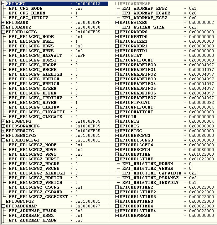
2) Do the FIFOs have to be enabled to read from the EPI bus? The datasheet is very good but not especially clear on this. The EPI block diagram suggests not.

3) Any idea why iRDY doesn't stall bus writes? Or does this only kick into life when the FIFOs are used?


  • Hello Pete,

    Can you share the following info

    1. How has the iRDY pin configuration been done at the GPIO?
    2. What is the IRDYDLY been configured as in EPIHB16TIME register?

    Regards
    Amit
  • Hi Amit,

    :) That's one of the two problems fixed. The EPIHB16TIME register hadn't been setup (must be the only register I've not read about!) and IRDYDLY was still at its POR value of 0x00 which is classed as being reserved. Writing IRDYDLY to 0x01 has made the iRDY bus stalling work. Thankyou Amit.

    Do you have any thoughts on why the EPI data can't be read? I've just tried again, now that iRDY works, but still I read 0x00 from the EPI data bus. All the other signals, including the READ pulse, look fine and have the correct timings.
  • Hello Pete

    Can you clear the CLKGATE bit and then check. I think I have responded to a similar post in the past where read path was dependent on the CLKGATE bit.

    Regards
    Amit
  • Hi Amit,
    I've just tried that but it still doesn't read. Just in case, I tried all four combinations of the CLKGATE and CLKGATEI bit in EPIHB16CFG but none makes a difference.

    Pete
  • Hello Pete

    Can you please share the EPI Configuration Sequence in the application code that you are using?

    Regards
    Amit
  • Hi Amit,
    The EPI config is:

    ; the naming here follows the datasheet for TM4C1294NCPDT
    EPI_CFG_SETUP:
    LDR R1, =EPI0_BASE+EPICFG
    LDR R0, [R1]
    ORR R0, R0, #EPICFG_MODE0+EPICFG_MODE1
    BICS R0, R0, #EPICFG_MODE2+EPICFG_MODE3 ; set EPI MODE to 0x03 for HostBus16
    ORR R0, R0, #EPICFG_BLKEN+EPICFG_INTDIV ; enable EPI controller + INT EPI clock divide
    STR R0, [R1]
    EPIHB16CFG_SETUP ; Setup EPI Host-Bus 16 Configuration (EPIHB16CFG), offset 0x010
    LDR R1, =EPI0_BASE+EPIHB16CFG
    LDR R0, [R1]
    BICS R0, R0, #EPIHB16CFG_MODE1
    ORR R0, R0, #EPIHB16CFG_MODE0 ; set HostBus16 mode=0x01 for non-multiplexed address & data busses.
    ORR R0, R0, #EPIHB16CFG_BSEL ; BSEL=0 16bit data. BSEL=1 8bit data.
    BICS R0, R0, #EPIHB16CFG_RDWS0+EPIHB16CFG_RDWS1 ; set RD wait states to 2
    BICS R0, R0, #EPIHB16CFG_WRWS0+EPIHB16CFG_WRWS1 ; set WR wait states to 2
    ORR R0, R0, #EPIHB16CFG_MAXWAIT7+EPIHB16CFG_MAXWAIT6 ; set a decent max wait time for WAIT (is this used?)
    BICS R0, R0, #EPIHB16CFG_BURST+EPIHB16CFG_RDCRE+EPIHB16CFG_WRCRE ; disable burst mode & PSRAM config read/write off
    BICS R0, R0, #EPIHB16CFG_ALEHIGH ; ALE polarity active low, but not be used here?
    BICS R0, R0, #EPIHB16CFG_RDHIGH+EPIHB16CFG_WRHIGH ; RD and WR strobe for CS0 is active low
    BICS R0, R0, #EPIHB16CFG_XFEEN+EPIHB16CFG_XFFEN ; External FIFOS disabled
    ORR R0, R0, #EPIHB16CFG_RDYEN ; use iRDY signal to stall transactions if needed
    BICS R0, R0, #EPIHB16CFG_IRDYINV ; 0= stall bus if iRDYis low 1=stall bus if iRDYis high
    BICS R0, R0, #EPIHB16CFG_CLKINV ; no EPI clock inversion
    BICS R0, R0, #EPIHB16CFG_CLKGATEI
    BICS R0, R0, #EPIHB16CFG_CLKGATE ;
    STR R0, [R1]
    EPIHB16CFG2_SETUP ; Setup EPI Host-Bus 16 Configuration (EPIHB16CFG2), offset 0x014
    LDR R1, =EPI0_BASE+EPIHB16CFG2
    LDR R0, [R1]
    BICS R0, R0, #EPIHB16CFG2_CSCFGEXT ; disable extended CSCFG bit field
    ORR R0, R0, #EPIHB16CFG2_CSCFG0
    BICS R0, R0, #EPIHB16CFG2_CSCFG1 ; set CSCFG to 0x01
    BICS R0, R0, #EPIHB16CFG2_MODE1
    BICS R0, R0, #EPIHB16CFG2_ALEHIGH ;
    ORR R0, R0, #EPIHB16CFG2_MODE0 ; set Chipselects Host Bus sub mode to 0x1 ADNONMUX
    BICS R0, R0, #EPIHB16CFG2_CSBAUD ; chip select same rates
    STR R0, [R1]
    EPIADDRMAP_SETUP
    LDR R1, =EPI0_BASE+EPIADDRMAP
    LDR R0, [R1]
    ORR R0, R0, #EPIADDRMAP_ERADR0+EPIADDRMAP_ERADR1 ;Ext RAM - CS0 maps to 0x6000.0000 & CS1 to 0x8000.0000
    ORR R0, R0, #EPIADDRMAP_EPADR0+EPIADDRMAP_EPADR1 ;Ext Periph - CS2 maps to 0xA000.0000 & CS3 to 0xC000.0000
    BICS R0, R0, #EPIADDRMAP_ECADR0+EPIADDRMAP_ECADR1 ;external code area not mapped
    BICS R0, R0, #EPIADDRMAP_ERSZ1
    ORR R0, R0, #EPIADDRMAP_ERSZ0 ; external RAM size to 64KB
    BICS R0, R0, #EPIADDRMAP_EPSZ1
    ORR R0, R0, #EPIADDRMAP_EPSZ0 ; external PERIPH size to 64KB
    STR R0, [R1] ; update EPIADDRMAP
    EPI_EPIBAUD_SETUP
    LDR R1, =EPI0_BASE+EPIBAUD
    MOV32 R0, #0x000000FF ; set temp values for EPI clock divide to slow it a lot for now
    STR R0, [R1]
    EPI_EPIHB16TIME_SETUP
    LDR R0, =EPI0_BASE+EPIHB16TIME
    LDR R1, [R0]
    ORR R1, R1, #EPIHB16TIME_IRDYDLY0 ; bus stall begins 1 EPI clock past iRDY sample
    STR R1, [R0] ; update EPIHB16TIME
    LDR R1, [R0]
    EPI_EPIRSIZE_SETUP
    LDR R1, =EPI0_BASE+EPIRSIZE0
    LDR R0, [R1]
    BICS R0, R0, #EPIRSIZE_SIZE0 ; Size = 16bits
    ORR R0, R0, #EPIRSIZE_SIZE1 ; Size = 16bits
    STR R0, [R1] ; set EPI SIZE to 0x02 = half word = 16bits
    NOP
    NOP
    NOP
    NOP
    NOP
    NOP
    NOP
    NOP ;Wait a min of 8 MPU cycles after end of EPI setup before use
    ; end of EPI Setup.

    Do say if you need the Equates that go with this code. The naming is the same as the datasheet for the TM4C1294NCPDT. Often bit clearing and setting is split between lines due to assembler limitations. After prototyping is complete these lines would be merged.

    Pete

    Adding a picture - this should detail the register settings after EPI initialisation with the above sequence:

  • Hello Pete

    Ouch. I was expecting a TivaWare based code. ASM code is rather tough to port over. If it is a CCS based project, then can you zip the project and send it over, else it may take me time (under current work load a lot) to be able to replicate the settings and see what the issue is.

    Regards
    Amit
  • Hi Amit,
    This is in IAR embedded workbench. Is there an assembler guide for CCS around, and I'll convert it for you. Or can you point me at some CCS Assembler code examples so I can take a look at what CCS expects.

    I can only do it in Assembler for you though. C drives me potty!

    Pete

  • Dear Amit,
    After a looooooong investigation and much reading I've discovered what's wrong, and why I can't read from the EPI interface, in either HB16 mode or General purpose mode. The GPIODEN settings for each pin/port used need to be set to enable before the EPI will read in. Sounds simple that doesn't it, but it's not mentioned anywhere in the EPI module chapter of the datasheet DS-TM4C1294NCPDT-15863.2743 SPMS433B.

    Enabling the GPIODEN settings when the pins have alternative functions enabled is mentioned in other modules such as the ADC, but not for the External Peripheral Interface. Unfortunately for me this is the first application I've written on the TM4C1294NCPDT. If there had been others I would of realised the problem. I think mention of GPIODEN is particularly worthy of the EPI initialisation section as its omission causes a problem that suggests you have a working module but other setup problems.

    Amit. In the course of solving the problem I have read the EPI chapter over and over and now have a list of minor corrections and recommendations that I would like to submit for inclusion in the next manual rev. How do I do that?

    Thankyou for solving the other problem of the bus stalling with iRDY. This has meant I can delete a section of code written to compensate for it not working. The icing on the cake for this code section. :)

    I have come across another potential noteworthy discovery in the EPI module that I need to record in case it's an issue to others in the future. That is; enabling IRDYDLY can cause the address map at 0x6000.0000 or 0x1000.0000 to disappear at the point in time when the EPIHB16TIME is written to. It seems to vanish when other bits in EPIHB16TIME have been changed from default at the same time especially (if memory serves me correctly) CAPWIDTH. I haven't stopped to investigate further but feel it worthy to mention it in case it offers a clue to those investigating such a fault in the future. And also to be aware of the read/write problems that the MCU has when using EPI in an address range 0x10000000 - mentioned in the erratum.

    Cheers Amit!

  • Hello Pete,

    While I appreciate your efforts and feedbacks (Seldom to posters engage in such joint activity), let me comment that I was thrown off track by the fact that "writes work fine" in the first post. With GPIODEN not set, that is not possible. So the write also must not have worked.

    Any further issues that you see with documentation and potential issue in EPI or any other peripheral on the device can be submitted on the forum (but do clearly mark each one out).

    Regards
    Amit
  • Hello Amit,

     "let me comment that I was thrown off track by the fact that "writes work fine" in the first post."

    The fact that the writes worked was what also threw me too. I've just had another good look at what's going on and still stand by what I've said. I did look into transfering it across to CCS for you but the syntax is significantly different and I need to move on with the project. So in order to try demonstrate what I see I've stripped out the code down to the bare miminum that replicates the problem, to try to give TI something they can experiment with, but it is in IAR embedded workbench form. All the files and setup are in the ZIP file attached. Also in the 'Pictures' directory of the attaached ZIP file are the screen shots of IAR EW for both runs of the code, showing setup and results for ports enabled and disabled. So if somebody there can set it up you can see both outcomes simply by uncommenting the two GPIODEN setup blocks in turn. You may have to change the JTAG probe setup but that's easy.

    I would also cite this post too:

    https://e2e.ti.com/support/microcontrollers/stellaris_arm/f/471/t/46341

    Now I know what the problem is it's much easy to find any previous similar problems! :-)

    One of two things will happen here I think; either it IS possible to write to the EPI interface with the GPIO disabled and TI will learn something, or it's not possible and I've slipped up somewhere, which I need to realise, as it's important when learning a new device.

    "Seldom do posters engage in such joint activity" . Yes I know, and it's a shame. Just because the interface to support is easily acquired I don't think people should be lame because of it. Whilst trying to solve a problem I also think it's a good idea to leave behind posts that are helpful to those that follow. I am indebted to the user old_cow_yellow on this forum for getting me started in ARM assembler bare metal startup as they posted a very helpful example. 99% of what's around is in C.

    Thankyou for your help Amit, much appreciated!

    Kind regards

    PeteTM4C1294NCPDT EPI GPIO Pin test.zip

  • Hello Pete,

    Thanks for the project. I will sure give it a try, to ensure we have a clean resolution to the post.

    Regards
    Amit