This thread has been locked.

If you have a related question, please click the "Ask a related question" button in the top right corner. The newly created question will be automatically linked to this question.

WDT0 phantom error causes random NVIC bus fault and Dog resets MPU.

Guru 55913 points
Other Parts Discussed in Thread: LM3S8971, TM4C1294NCPDT

This post a continuation from other posts all gaining evidence in the mystery - who done it and why remains opaque.

Almost seems as if a trace on EK-TM4C1294i3-XL PCB could be crossed with some other trace or internal NVIC line/register.

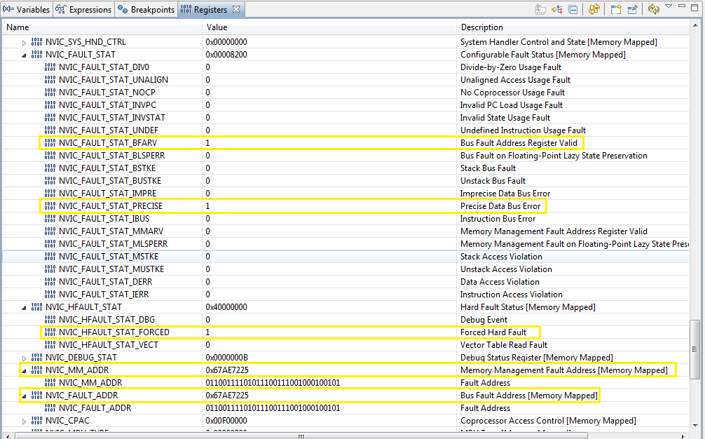
Seemingly out of place the EPI0 peripheral is not configured yet the External power control for EPI0 in CCS debug is showing set 1 enabled. That EPI0 happens to fall on the NVIC fault address more than one time (0x67AE7225).

Control register 7 has RESC=0x8 or WDT0 interrupt was cause of the MPU reset.  

Previous posts to issue:

https://e2e.ti.com/support/microcontrollers/tiva_arm/f/908/p/425490/1520868#1520868

https://e2e.ti.com/support/microcontrollers/tiva_arm/f/908/p/425490/1519603#1519603

Bus Fault:


  • May this reporter "applaud" the very well designed thread title?   Complexity of your issue demands those of pay grade far beyond this reporter...

  • Hello BP101,

    BP101 said:
    Duplicated fatal buss error with WDT0 remains constant:

    Note that the CCS refresh is not set, which may keep the last read value on the screen with highlight ON.

    BP101 said:
    External power control for EPI0 in CCS debug is showing set 1 enabled

    Do you mean SYSCTL.PCEPI. If yes then it set by default and not by any code behavior.

    Lastly if WatchDog is indeed the cause of reset, what is the value of the SYSCTL registers like RSCLKCFG when the code jumps?

    Regards

    Amit

  • The highlight values were updated and asserted right after clicking Pause during the IntFault() trap.

    Will try refresh to see what if anything changes in that behavior.

    Part of this issue is understanding the dog and how he behaves when ANY module suddenly stops responding. Discovered setting WDT0 to not reset MPU, Halts the MPU so the machine state can be examined. That WDT0 was part of migrated SW and is now also covering Exosite IOT code.

    Traced issue to last pending interrupt is EMAC0 and (EMAC_INT_RX_NO_BUFFER), was not WDT0 interrupt as earlier believed. Debug register Interrupts show the Bits not the actual interrupt that asserted. Hard to grasp that when seeing the word Interrupt first then Bits[xx]  following. So we then have to go to data sheet and cross examine the interrupt table to convert the position. Part of the learning curve built into CCS.

    Added the EMAC_INT_RX_NO_BUFFER flag into the WDT0 interrupt handler and it constantly interrupts.

    The EMAC_INT_RX_NO_BUFFER has been set to interrupt, in belief that the DMA engine then sets the RESD0 descriptor bit position to indicate an interrupt occurred. That topic is not well discussed in the datasheet text and leaves one to assume they must set the interrupt source NVIC in order for the flag to ever assert. Oddly there in no such interrupt  bit RESD0 = EMAC_INT_RX_NO_BUFFER so the abnormal interrupts count never increments.

  • BTW: This project is using Tivaware driver library 2.1.1.71 as a project dependency.

    EMAC_INT_RX_NO_BUFFER | EMAC_DMARIS_RU both == 0x0000.0080 and makes WDT0 fault continuously.

    Oddly CCS debug continuous refresh posts DMARIS_RU/RI flag when suddenly MPU Halts. That behavior tends to infer the bit position in the [Int_Rx _No_Buffer] flag is incorrect.

    Edit: Above WDT0 test must use (&=) in the if test as the compiler will not compare the values (==) with the register contents.

  • Hello BP101,

    It seems that there is no Receive Buffer available for offloading the data from the EMAC Engine in RDES which is triggering the interrupt. Could it be that the process of allocating buffers is slower than the input data?

    Regards
    Amit
  • Think RBU is the after math of the disaster in memory NVIC Bus Fault 0x67xx.xxxx. Above post WDT0 interrupt required (&=) order to compare and test the No_Buffer/No_RU register flags. Dog is no longer barking continuously. Strange the compiler can not (if) test a register contents retrieved value (==) with a static variable.

    DMA engine Tx descriptors keep up with much faster Telnet client TCP 23 transmitting near 25MBPS. Rx buffers mostly ACK packets from Telnet client and it can run continuously without any issues when not transmitting IOT into the cloud.

    For reproducing No RX Buffers error the Telnet client is not running.
    The only receive packets (98 bytes) each every cycle, HTTP 204 return status from Exosite. For testing we only WRITE stats or TX (305 bytes) every cycle to IOT server.

    Setting the DMA priority fixed or Rx = [EMAC_BCONFIG_FIXED_BURST | EMAC_BCONFIG_PRIORITY_FIXED] renders no different result. The main difference is IOT uses (ringbuf.c) to save data into SRAM and that atomic index pointer seems to suddenly change the address to EPI0. Course the DMA engine is going to halt since EPI0 is an illegal address vector. Seems there could be issues with execution timing in (ringbuf.c).

    After adding a delay time before writing bytes into the RX buffer (ringbuf.c) extends the time when bomb drops. If anything (tiva-tm4c129.c) could be running to fast in order to keep up in supplying Buffs for the high speed telnet client. Systick period is (120mHz/300) LWIP timer interval. Any slower, when both clients are running chained the speed of GUI scopes is far to slow. Effectively we have two interval timers in (lwiplib.c) for calling each client module in the same interrupt context using Systick. So when the Telnet client runs with IOT it slows down the execution timing of (ringbuf.c) and the time bomb moves further out in time with it.

    Amit sir, how do we make this bomb go away?

    BTW: Can not locate the (qs_iot) project updates in the 3.5GB bundle Tivaware 2015 version 12.573 or 2.1.1.71.

  • Could it be that the process of allocating buffers is slower than the input data?

    Try to describe a WA:  Seemingly the host process was running so fast the Ring Buffer was trying to fetch the contents from the EnetBuffer before the OWN bit was  cleared in the RX descriptor. The watchdog detected the random fault resetting the MCU every 2nd time out.  The RX/TX FIFO has a 64 byte threshold, ignored in Store & Forward DMA operation mode. We believe  the RX/TX 64 byte threshold is incorrectly configured in most all SW examples confusing the reader of Tivaware any all text. That may be what allows or leads up to the Blocking fault causing a fatal bus error.

    (eth_client_lwip.c) sets the event FLAG_RECEIVED in the exoHAL 50 byte FIFO threshold. That does not mean the host OWNS the data in the FIFO SRAM when the flag is not Blocking. Basically RingBuffer read/write need be delayed in the byte transfer cycle setting the host index pointer into the FIFO SRAM at a 55 byte deep threshold so (ringbuf.c) synchronizes with the OWN bit status changes during blocking mode.

    That makes the host become synchronous with the DMA and LWIP interval timers. Perhaps a better blocking method would indicate the OWN bit is clear for (ringbuf.c) so he doesn't violate DMA arbitration rules.  For now the WA adds a double nested delay loop in the  read/write (for) loop slowing down read/write into SRAM. Also increased the blocking delay divisor from 10 to 80 and for once saw a timeout message pass by instead of just halting the MCU.

    ~~~~~~~~~~~~~~~~~~~~~~~~~

        uint32_t ui32Delay = 0;
        uint32_t ui32Count = 2;
    	 
        /* Double nest a delay between
     	 *  successive buffer reads/writes */
    	 while(ui32Count > 0)
    	 {
    	   while(ui32Delay < 0xFFFFFFFF)
               {
    	        ui32Delay++;
                }
    	   ui32Delay = 0;
    	   ui32Count--;
    	 }
            pui8Data[ui32Temp] = RingBufReadOne(psRingBuf);
        }
    }
  • All hail (another) self-awarded, "Verify!"

    May we question if this "fix" has not unduly "s l o w e d" the process - AND if it has "passed the test of time?"

    "One time seeing" a "timeout message" is unlikely to warrant, "bullet-proof" verify!
  • The audience claps as the seconds count rises far past 500 or even 700 seconds void of MCU halt. Well passing 13390 seconds IOT online not a single MCU reset. Far as performance goes a test for blocking is always better than added delays.

    Mon ami you miss the bigger picture is targeting the functions causing the condition that most unequivocally leads to a bus fault. That has taken over 3 grueling months, long hours trial error etc.. after discovering something was wrong. Until recently CCS debug would not allow any register access nor effectively erase, flash, often not halt the DAP - unknowingly while the bulldog lies awake.

    Stellaris LM3S8971 MCU never acts that way, CSS watchdog awake no issues. Who would ever guess we need to set debug stall enable watchdog and add a long 1 second delay after asserting the MOSC or the DAP could not halt the MCU. Those conditions don't add up to any kind of logic pointers that lead to a successful debug discovery.
  • Indeed - this reporter/friends/others - "hope" your analysis "holds" - wins the blessing of Amit.

    While grateful to receive your "free pass" for "low orbital, BP mission #1" this reporter's feet remain (2 part epoxied) solidly to terra firma - until & if - "latest/greatest" BP "fix" passes "test of time."     (may I (still) keep the "BP in orbit" T-Shirt...and (generic) Dramamine?)

    One can only imagine - the multitude of "treasures" - arriving Amit's doorstep...   (off camera - to Amit...."suggest you deepen your moat")

  • - "latest/greatest" BP "fix" passes "test of time."   

    Timing issues in hardware that directly impact software is not an uncommon situation in the computer industry dating back to the 1980's. Quite evident is time wasted for lack of regression tested Tivaware, much merely rewritten Stellarisware that executed code at a far slower MOSC.

    Have been exposed to similar issues during MCU migrations of Cadol high level language written for Intel processors 8080 - 80286.  Often instructed to employ nested delay loops where code would go bonkers for no apparent reason. That hardware used a Intel DMA controller that was bit loopy at times.

    Case this bus fault, TM4C1294NCPDT MCU has EMAC DMA arbitration timing issues effecting software at a higher level. Most evident DMA arbitration turn around access timing in the TX/RX controller at Systick 2.5us - 3.3us - somehow allows SW collisions in SRAM.

    TI remains silent this issue, likely a witness to very same calamity not know what be causing. Rest assured HW arbitration timing can be corrected via added SW delay loops. Recent witness high level SW SENT_FLAG delay buys time for DMA to transfer the RX frame to SRAM immediately after an TX operation, OMIT the bus error that would typically follow. Sacrifices for the high speed advantage are made in the name of sanity  

    Not all is Kosher in HW & SW play time and embedded SW needs to be more robust at these faster MOSC clock speeds.

    //*****************************************************************************
    //
    //! Returns the length of a null-terminated string.
    //!
    //! \param s is a pointer to the string whose length is to be found.
    //!
    //! This function is very similar to the C library <tt>strlen()</tt> function.
    //! It determines the length of the null-terminated string passed and returns
    //! this to the caller.
    //!
    //! This implementation assumes that single byte character strings are passed
    //! and will return incorrect values if passed some UTF-8 strings.
    //!
    //! \return Returns the length of the string pointed to by \e s.
    //
    //*****************************************************************************
    size_t
    ustrlen(const char *s)
    {
            size_t len;
            uint32_t ui32Delay = 0;
            uint32_t ui32Count = 20;
        //
        // Check the arguments.
        //
        ASSERT(s);
    
        //
        // Initialize the length.
        //
        len = 0;
    
        //
        // Step throug the string looking for a zero character (marking its end).
        //
        while(s[len])
        {
            /* Double nest a delay between
         	 *  successive buffer reads/writes */
        	 while(ui32Count > 0)
        	 {
        	   while(ui32Delay < 0xFFFFFFFF)
                   {
        	     ui32Delay++;
                   }
        	   ui32Delay = 0;
        	   ui32Count--;
        	 }
    			//
    			// Zero not found so move on to the next character.
    			//
    			len++;
            }
    
          return(len);
     }


  • BP101 said:
    TI remains silent this issue, likely a witness to very same calamity not know what be causing.

    Try as you might - suppressing your "urban speak" - cannot be fully restrained!    May we note (Brett approved) "urban conjugation" of the verb form, "to be" ... I be, you be, he/she be, we (all) be, etc.  

    Kings/Queens English may suggest, "What is causing" as more general/(correct) usage...   (not that there's anything wrong w/urban usage/dialect...although you may wish to (bit) "mute" when visiting Chi-based VCs)

    Till skilled others confirm your "fix" - this reporter (with reluctance) declines (free) passage upon BP #1's maiden voyage - and moves to stronger (4 part) epoxy to strengthen footgear's attachment to ground...   (we be stick'in)

  • You forgot is be, was be, could be, mostly true. Only desire to wake sleeping giant such bean stalk growing inside his kingdom, will not protect the golden goose for long. Better get cracking on code patches start regression testing Tivaware at high speed Systick interrupt timings. Might there be TM4C speed limitation not being disclosed, such lays dormant for unsuspecting coders burned at the stake.

    Watchdog-1 now wagging tail front door as IOT prints (tStats) on his watch.

    All alone in pushing envelope TM4C high speed MCU intended for high speed, is be not working well at high speed. :(


  • BP101 said:
    All alone in pushing envelope TM4C high speed

    One hopes that Amit, "Be: check'en/test'en/report'en..." 

  • Default watch dogs configuration masked an initial early bus fault, automatically resetting the MCU. Reset after POR is hardly noticeable until one disables WDT0/WDT1 MCU reset enable. More often POR ends up in a FaultISR - requires user to mash reset button a few times order to clear the fault, get things rolling. Note any startup random faults are coded to clear automatically by SW after all peripherals have been initialized and the event occurs shortly after clearing said faults.

    The EMAC0 DMA is a likely suspect conspirator of SRAM bomb dropping. The odd thing is typical Systick=SYSCLK/100= 83.3us period @1.2Mhz and Sysclk/300 = 2.5us @400Khz which runs TCP stack faster than does 1.2mHz . Systick interrupt period works backwards from logic in RC time constants and F=1/p mostly useless, confuses anyone with an electronics background. The shorter Systick period produces a longer time between reset interrupts than does the longer period.

    Not sure if that describes proper Systick timer behavior. Blinky calls are behaving the same way, gives us a visual feed back of the interrupt interval in LED pulse rate. The shorter Systick timer intervals produce longer periods of LED off time.
  • Systick is ARM's very basic, 24 bit, downcounting, counter/timer which, "Clears on write" and "Wraps on zero."

    Many (most) who experience the inconsistency you report "miss" Systick's 24 bit data capacity.    Might you fall in that camp?

    In your time here - it's likely that you've read many posts - noting the superiority of ARM's (real) Timer resource for precise timing measurements.    Systick's "expected behavior" may be breached by higher priority events - especially those which require regular program interrupts.

    To insure mastery of, "Systick" does it not make sense to load basic, "Blinky" - by itself - with Systick providing each/every of the timed events - and test/observe.    Such gives Systick the greatest chance to succeed - and proves your understanding & code implementation...

  • Might have stated all timers TM4C exhibit the very same odd timing behavior. Witness LED blink rate and GUI scope horizontal scroll rate decrease in speed with higher frequency period divisors of SYSCLK. Oddly the watchdog timers seem to follow closely F=1/p or SYSCLK/2=16.6us (60mHz). UARTprintf message post watchdog timeout as to know when to punch that dog in many SW places. SYSCLK/50 (2.4mHZ) = 41.6us period. That is logical, a shorter period = a higher frequency not the opposite behavior of the other timers exhibit.

    Take 1000/100=10 for example and F=1/p seemingly ends up at 0.1 yet 120mHz SYSCLK/100 don't equate to milliseconds rather the reset wrap period will be in microseconds.

    On the other hand pure assembler SysCtlDelay (SYSCLK * 1 ) produces near 1/2 second delay period, no divisor will Do any such extend delay such as multiplier is required. So we have frequency normalization in pure assembler in the hard coded delay timer loops.
  • Is it not reasonable to expect that many (others) would have noted this, "odd timing behavior?"    (Ans: mais certainement, mon ami)

    Indeed - you have past made "finds" - but I cannot (for a second) believe so grave a "misfire" could escape more general note.  That's just not possible!

    Might you provide the shortest "C" code example which illustrates your plight?    Even those "burdened/disinterested" may prove curious enough to load your example - and test - and then "advise & assist" here!

    I'd place (very tall) "stack of black chips" that issue is your code implementation - or "misinterpretation of results" - not any (universal) miscue w/in every TM4C Timer & Systick!

    Dawns that you may have inadequately noted that SysTick observes a strict, "down-count only" protocol - thus a "higher" SysTick count value - most often indicates a shorter "deviation" from its initial, pre-load value!    (And that "seemingly" higher SysTick value [when compared against its higher, "pre-load" value] denotes a "shorter" elapsed count or time - does it not?)     Could this - in fact - be your issue?     (only thing which makes sense - to my mind)    Timers - which may downcount similarly - may exhibit those very same findings.

    While your word pictures attempt to "justify" your report - they pale when compared to the requested, "minimal code example/resource utilization listing" - which demonstrates your "breakthrough" discovery.     Odds even higher on your, "Miss of downcount" than on (another) failed Triple Crown...   (tech diagnosis [w/supporting justification] & interweave of vital current event - where else can you get such?)

  • Seriously code is as shown in above post  P=(SYSCLK/value) how much more simple need it be. Unless we ever take time to compare apples to apples we get questionable results. Visuals of bytes & lines per-second digital read out UARTprintf() such time to screen is easy to perceive under laying timers.

    Finally got to bottom of all this mayhem being interrupt priority in LWIP timer set a higher level than EMAC0 DMA cause NVIC bus error. Seemed logical the SW was doing far more computing with data than the HW. Might have deduced sooner if not for last few days seeing random abnormal interrupts (0x98315), (0x98307), (0x32896) being reported by EMAC0.  

    Lately after adding nested delay loops in (ringbuf.c) the phantom bus error started to show up just after POR.

    The programing note below found in (ExoHAL)  none objectively states the Systick priority (0x80) need be set above EMAC0 priority (0xC0).

    BTW: We are not using Systick interrupt for the LWIP timer call but testing found Systick can also cause the NVIC bus error as configured below.


    #if NO_SYS
            //
            // Configure SysTick for a periodic interrupt.
            //
            SysTickPeriodSet(g_ui32SysClock / SYSTICKHZ);
            SysTickEnable();
            SysTickIntEnable();
    
            //
            // Turn on interrupts.
            //
            IntMasterEnable();
    
            //
            // Set the interrupt priorities.  We set the SysTick interrupt to a
            // higher priority than the Ethernet interrupt to ensure that the file
            // system tick is processed if SysTick occurs while the Ethernet
            // handler is being processed.  This is very likely since all the
            // TCP/IP and HTTP work is done in the context of the Ethernet
            // interrupt.
            //
    
            IntPriorityGroupingSet(4);
            IntPrioritySet(INT_EMAC0, ETHERNET_INT_PRIORITY - 0xC0);
            IntPrioritySet(FAULT_SYSTICK, SYSTICK_INT_PRIORITY - 0x80);
    #endif

  • Might it be Systick has the highest or no priority by design such that it exists at the NVIC level. Might like to add this fatal bus error can be verified by setting up any basic 16bit timer interval period (SYSCLK/300) assigned to a higher interrupt priority than EMAC0. To that point a higher priority timer interrupt existing over EMAC0 will be serviced FINL by NVIC and randomly desynchronize the FIFO DMA with SRAM causing a NVIC bus error

  • BP101 said:
    Might have stated all timers TM4C exhibit the very same odd timing behavior

    Have you not just run - fast/furiously - from your (above) claim that ALL TM4C Timers and Systick are, "odd" and appear plagued w/"reciprocal time results?"

    State-shifting - sometimes your "norm" does not ease your assistance.    Again - have you not "missed" the impact of Systick & Timer, downcount?

  • ■ Count up or down 0xFFFF (Up Counter Modes, 16-/32-bit) 0x0000 | (Down Counter Modes, 16-32-bit)

    More of an strange observation could have been leading to bus error. Will investigate the why cause, might be as you suspect counting Down versus Up.  Point well made seems plausible the shorter period is wrapping sign from 0x000 to -0xFFFF and timer is acting backwards with the period. CB1 did mention interrupts above post, walking that line keeps focus to issue bus error was not to far off track questions as to why timers are suspect.

    Switch focus to the NVIC interrupt priority set (group 4) Timer2A INT39 and the LWIP timer was assigned priority 0x10 well above EMAC0 0xC0 INT56. Currently Timer2A has been re-assigned directly NIL 0x0A immediately above EMAC0.  We abandon Systick for the LWIP timer call a few months ago and switched it back last night to test once again. Systick INT15 priority 0x80 directly above EMAC0 0xC0.  Question what was so wrong of Timer2A assigned priority 0x10?

    The priority grouping rule seems to imply mandatory NIL in multiple interrupts handling that occur in the same group. Such as Systick complies with NIL no matter what the exception INT 0x15 priority is set to. Assigning Timer2A priority 0x10 while being higher priority than EMC0 must some how violate NIL rules and caused random abnormal interrupts handling in EMAC0 DMA engine. One other comes to mind, lastly moved WDT1 to lowest INT priority 0xF0 and removed his INT service vector to function print all tStats last night 1am but still had the NVIC bus error.

    DS: If multiple pending interrupts have the same group priority, the subpriority field determines the order in which they are processed. If multiple pending interrupts have the same group priority and subpriority, the interrupt with the lowest IRQ number is processed first.

        /* Periodic Timer-2A for LWIP interval timer functions.
         * Handles the EthernetSendRealTimeData().
         * Configure the 16-bit Timer-2A for 400kHz 2.5us. */
        ROM_TimerClockSourceSet(TIMER2_BASE, TIMER_CLOCK_SYSTEM);
        ROM_TimerConfigure(TIMER2_BASE, TIMER_CFG_A_PERIODIC);
        ROM_TimerLoadSet(TIMER2_BASE, TIMER_A, g_ui32SysClock / 300);
        ROM_TimerIntEnable(TIMER2_BASE, TIMER_TIMA_TIMEOUT);
        ROM_TimerEnable(TIMER2_BASE, TIMER_A);
        ROM_IntEnable(INT_TIMER2A);

  • Again your tendency to "shape-shift" makes assistance very difficult.

    You made the claim - but have failed to substantiate - that MCU Timers and Systick behave, "oddly."    You noted a, "reciprocal" like timing pattern.

    Proposed was a limited new program - enabling your total focus upon the set-up/config & examination of just "Systick."   And this simple - "KISS" test & evaluation has unleashed a torrent of "new issues" and received not one word in response.

    Some do try to assist - KISS is very well known to work - "shape-shifting - fast/furiously as is your want" is hard for you to limit and frustrating for your helpers.   (we note most have, "fled this scene...")

  • What you call shape shifting misses the point entirely, said blinky is be incorporated in existing code. Exception code (11) above post discovery process provided evidence specific to Exosite IOT code R/W into SRAM.  Again not currently using Systick in the program piece causing code (11), using term Systick only served to generalize a issue exists in the accessing timings of certain peripherals @2.5us -3.3us.  How other than F=1/p can period be extrapolated in all wrap counters, if other formula exists datasheet leaves such formula missing. What say CB1 silent this find to use F=1/p in setting counters up/down clock period works flawlessly for determining PWM period - BP101 feels to be right on point and focus.

    Learning of late how systemic timing errors involving NVIC interrupts can be tricky to reveal underlying cause. While we can seemingly make an error disappear by moving Rubik cube blocks it may only lead to masking an underlying cause and not actually proving what is to blame HW or SW. Frankly spent far to much time getting to the nitty gritty, first assuming higher pay grade individuals have documented and discovered such stumbling blocks to begin with.

    Point in case, by removing added timing delays in 2 specific SW locations, right  after EMAC0  TX send (blocking) into RX, the other prior to EEROM reads each depending on added delay time can be made to cause a random exception  (11) INT5 =  (Bus Error).

    By our accounting method, have to say this focus method works best for showing results. Amit mute here and several other posts might to be seeing the light discovered access timing issues & WA tricks of the trade.

    Silent most all in suggesting bus access timing issues exist around EEROM, DMA, SRAM @2.5us - 3.3us. Now quite obvious missing any litmus testing to reveal maximum data bus timing speeds in TM4C. All this conundrum over NDNR Stellaris proven LM3S8971.  Seemingly just as oblivious to this condition as the person Burned at the stake left tirelessly trying to determine what and why. Finally glad to have IOT working playing nice with others in the TCP pool.

  • What myself - many (all?) others believe to, "miss the point entirely" is your claim that all TM4C Timers & Systick, "Behave oddly."

    Wish you well - I'd gladly assist if/when "KISS" (as repeatedly requested) may be engaged.    Bon chance, mon ami.