Other Parts Discussed in Thread: LMC6482
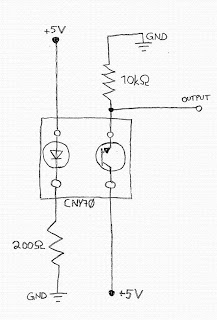
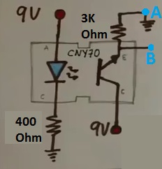
Above figure CNY70 (reflective optical sensor) wiring diagram that I found in the internet. I'm using TM4C123 series MC. Have 2 questions:
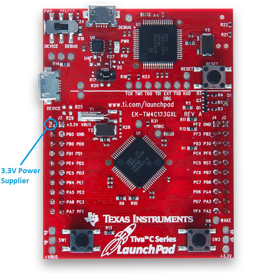
1) Can I use the 3.3V output of the microcontroller rather than 5V? If you suggest external voltage source, which components should I use to protect the MC?
2) As you see I'm quite noob at electronics, and electronic components. I've started taking Edx: 6.002x Circuits and Electronics. Which courses, or books do you suggest further to study?
Thank you