This thread has been locked.

If you have a related question, please click the "Ask a related question" button in the top right corner. The newly created question will be automatically linked to this question.

CAN communication with single TIVA C Launchpad , between two CAN port

Other Parts Discussed in Thread: EK-TM4C123GXL, ISO1050

Hello,

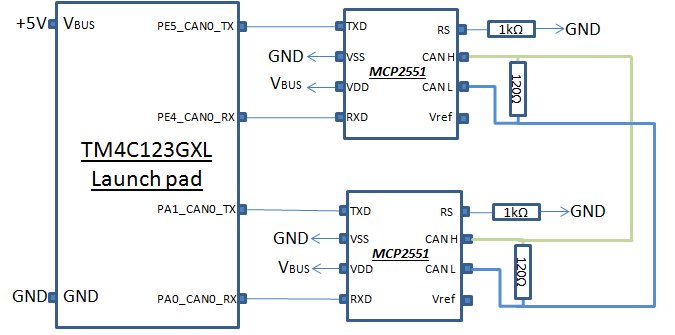
I want to learn about CAN communication. I am using TIVA TM4C123GXL Launchpad. After reading some previous posts about CAN I got the idea that I need two TIVA C boards for ideal CAN configuration. Since I don't have another one, is it possible to develop the communication on a single port but between two ports. As shown in below drawing:

Another doubt is can I use the Simple_Rx and Simple_Tx code on the same controller. I have got sample transceiver IC SN65HVD1050D , will it work instead of MCP2551.

Please let me know is it a workable thing or not..?

Thank you.

  • Might you have to insure that PA0/PA1 are not "in play" via the ICDI MCU? Otherwise - in general - yours looks, "Good for Gov't Work."

    (yet I'd still "stand back" - @/around, Power On...)
  • Hello Anup,

    Besides the point cb1 raised, a code that is developed for 2 or more controllers in a single micro, requires that the code partitioning be done very carefully. Otherwise you may end up cross referencing variables.

    Also SN65HVD1050D should work.

    Regards
    Amit
  • Amit Ashara said:
    Otherwise you may end up cross referencing variables.

    That's great - and something (completely) missed by this inept code reporter.

    I recall our great success w/simpleRX.c and simpleTC.c - but only when/where "talking" to a real CAN remote thru a xcvr.

    Accessing that code - as you well note - via 2 paths - must indeed be carefully considered.

    As this has NO (or a most unlikely) real world benefit - acquisition of a proper CAN slave or 2nd LPad appears a far superior path.   (i.e. spend one's time focused on the real world application - not those confined to "Spend no money and/or Fantasy-Land.")

  • Hello,

    Regret for delayed reply.

    So I have bought a new EK-TM4C129 Launchpad.

    Now for CAN communication I am trying to implement simple Tx code on Ek-TM4C123GXL Launchpad (PE4 and PE5 as Rx and Tx) and EK-TM4C129 Launchpad for simple Rx example.

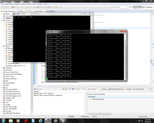
    Simple Tx code is working fine on TM4C123 Launchpad, pulses are coming on Oscilloscope and Msg Count seen on UART (I am using Putty).

    But Simple Rx code in TM4C129 Launchpad does not show anything on UART . Tx and Rx both remain high continuously.

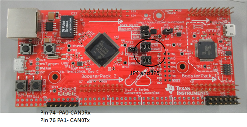
    I am using CAN0 (PA0 and PA1) and UART 2. I have changed the jumper position to vertical.

    Below is the code:

    #include <stdint.h>
    #include <stdbool.h>
    #include "inc/hw_memmap.h"
    #include "inc/hw_types.h"
    #include "driverlib/gpio.h"
    #include "drivers/pinout.h"
    #include "driverlib/pin_map.h"
    #include "driverlib/rom.h"
    #include "driverlib/rom_map.h"
    #include "driverlib/sysctl.h"
    #include "driverlib/uart.h"
    #include "utils/uartstdio.h"
    
    
    #include <stdbool.h>
    #include <stdint.h>
    #include "inc/hw_can.h"
    #include "inc/hw_ints.h"
    #include "inc/hw_memmap.h"
    #include "inc/hw_types.h"
    #include "driverlib/can.h"
    #include "driverlib/gpio.h"
    #include "driverlib/interrupt.h"
    #include "driverlib/pin_map.h"
    #include "driverlib/sysctl.h"
    #include "driverlib/uart.h"
    #include "utils/uartstdio.h"
    
    
    //*****************************************************************************
    //
    // System clock rate in Hz.
    //
    //*****************************************************************************
    uint32_t g_ui32SysClock;
    
    //*****************************************************************************
    //
    // The error routine that is called if the driver library encounters an error.
    //
    //*****************************************************************************
    #ifdef DEBUG
    void
    __error__(char *pcFilename, uint32_t ui32Line)
    {
    }
    #endif
    
    //*****************************************************************************
    //
    // Configure the UART and its pins.  This must be called before UARTprintf().
    //
    //*****************************************************************************
    //*****************************************************************************
    //
    //! \addtogroup can_examples_list
    //! <h1>Simple CAN RX (simple_rx)</h1>
    //!
    //! This example shows the basic setup of CAN in order to receive messages
    //! from the CAN bus.  The CAN peripheral is configured to receive messages
    //! with any CAN ID and then print the message contents to the console.
    //!
    //! This example uses the following peripherals and I/O signals.  You must
    //! review these and change as needed for your own board:
    //! - CAN0 peripheral
    //! - GPIO port A peripheral (for CAN0 pins) Anup
    //! - CAN0RX - PA0
    //! - CAN0TX - PA1
    //!
    //! The following UART signals are configured only for displaying console
    //! messages for this example.  These are not required for operation of CAN.
    //! - GPIO port A peripheral (for UART0 pins)
    //! - UART2RX - PD4
    //! - UART2TX - PD5
    //!
    //! This example uses the following interrupt handlers.  To use this example
    //! in your own application you must add these interrupt handlers to your
    //! vector table.
    //! - INT_CAN0 - CANIntHandler
    //
    //*****************************************************************************
    
    //*****************************************************************************
    //
    // A counter that keeps track of the number of times the RX interrupt has
    // occurred, which should match the number of messages that were received.
    //
    //*****************************************************************************
    volatile uint32_t g_ui32MsgCount = 0;
    
    //*****************************************************************************
    //
    // A flag for the interrupt handler to indicate that a message was received.
    //
    //*****************************************************************************
    volatile bool g_bRXFlag = 0;
    
    //*****************************************************************************
    //
    // A flag to indicate that some reception error occurred.
    //
    //*****************************************************************************
    volatile bool g_bErrFlag = 0;
    
    //*****************************************************************************
    //
    // This function sets up UART0 to be used for a console to display information
    // as the example is running.
    //
    //*****************************************************************************
    void
    InitConsole(void)
    {
        //
        // Enable GPIO port A which is used for UART0 pins.
        // TODO: change this to whichever GPIO port you are using.
        //
       // SysCtlPeripheralEnable(SYSCTL_PERIPH_GPIOA);
        SysCtlPeripheralEnable(SYSCTL_PERIPH_GPIOD); //anup
    
        //
        // Configure the pin muxing for UART0 functions on port A0 and A1.
        // This step is not necessary if your part does not support pin muxing.
        // TODO: change this to select the port/pin you are using.
        //
      //  GPIOPinConfigure(GPIO_PA0_U0RX);
      //  GPIOPinConfigure(GPIO_PA1_U0TX);
    
        GPIOPinConfigure(GPIO_PD4_U2RX);
        GPIOPinConfigure(GPIO_PD5_U2TX);
    
        //
        // Enable UART0 so that we can configure the clock.
        //
      //  SysCtlPeripheralEnable(SYSCTL_PERIPH_UART0);
        //anup
        SysCtlPeripheralEnable(SYSCTL_PERIPH_UART2);
    
        //
        // Use the internal 16MHz oscillator as the UART clock source.
        //
      //  UARTClockSourceSet(UART0_BASE, UART_CLOCK_PIOSC);
        //anup
        UARTClockSourceSet(UART2_BASE, UART_CLOCK_PIOSC);
    
        //
        // Select the alternate (UART) function for these pins.
        // TODO: change this to select the port/pin you are using.
        //
      //  GPIOPinTypeUART(GPIO_PORTA_BASE, GPIO_PIN_0 | GPIO_PIN_1);
        //anup
        GPIOPinTypeUART(GPIO_PORTD_BASE, GPIO_PIN_4 | GPIO_PIN_5);
    
        //
        // Initialize the UART for console I/O.
        //
        UARTStdioConfig(2, 115200, 16000000);
    
       // UARTStdioInit(0);
    
         UARTprintf("simple CAN BUS RX\r\n");
    }
    
    //*****************************************************************************
    //
    // This function is the interrupt handler for the CAN peripheral.  It checks
    // for the cause of the interrupt, and maintains a count of all messages that
    // have been received.
    //
    //*****************************************************************************
    void
    CANIntHandler(void)
    {
        uint32_t ui32Status;
    
        //
        // Read the CAN interrupt status to find the cause of the interrupt
        //
        ui32Status = CANIntStatus(CAN0_BASE, CAN_INT_STS_CAUSE);
    
        //
        // If the cause is a controller status interrupt, then get the status
        //
        if(ui32Status == CAN_INT_INTID_STATUS)
        {
            //
            // Read the controller status.  This will return a field of status
            // error bits that can indicate various errors.  Error processing
            // is not done in this example for simplicity.  Refer to the
            // API documentation for details about the error status bits.
            // The act of reading this status will clear the interrupt.
            //
            ui32Status = CANStatusGet(CAN0_BASE, CAN_STS_CONTROL);
    
            //
            // Set a flag to indicate some errors may have occurred.
            //
            g_bErrFlag = 1;
        }
    
        //
        // Check if the cause is message object 1, which what we are using for
        // receiving messages.
        //
        else if(ui32Status == 1)
        {
            //
            // Getting to this point means that the RX interrupt occurred on
            // message object 1, and the message reception is complete.  Clear the
            // message object interrupt.
            //
            CANIntClear(CAN0_BASE, 1);
    
            //
            // Increment a counter to keep track of how many messages have been
            // received.  In a real application this could be used to set flags to
            // indicate when a message is received.
            //
            g_ui32MsgCount++;
    
            //
            // Set flag to indicate received message is pending.
            //
            g_bRXFlag = 1;
    
            //
            // Since a message was received, clear any error flags.
            //
            g_bErrFlag = 0;
        }
    
        //
        // Otherwise, something unexpected caused the interrupt.  This should
        // never happen.
        //
        else
        {
            //
            // Spurious interrupt handling can go here.
            //
        }
    }
    
    //*****************************************************************************
    //
    // Configure the CAN and enter a loop to receive CAN messages.
    //
    //*****************************************************************************
    int
    main(void)
    {
        tCANMsgObject sCANMessage;
        uint8_t pui8MsgData[8];
    
        //
        // Set the clocking to run directly from the external crystal/oscillator.
        // TODO: The SYSCTL_XTAL_ value must be changed to match the value of the
        // crystal used on your board.
        //
      //  SysCtlClockSet(SYSCTL_SYSDIV_1 | SYSCTL_USE_OSC | SYSCTL_OSC_MAIN |
                 //      SYSCTL_XTAL_16MHZ);  anup
    
        g_ui32SysClock = MAP_SysCtlClockFreqSet((SYSCTL_XTAL_25MHZ |
                      SYSCTL_OSC_MAIN | SYSCTL_USE_PLL |
                      SYSCTL_CFG_VCO_480), 120000000);
    
    
        //
        // Set up the serial console to use for displaying messages.  This is
        // just for this example program and is not needed for CAN operation.
        //
        InitConsole();
    
        //
        // For this example CAN0 is used with RX and TX pins on port B4 and B5.
        // The actual port and pins used may be different on your part, consult
        // the data sheet for more information.
        // GPIO port B needs to be enabled so these pins can be used.
        // TODO: change this to whichever GPIO port you are using
        //
        SysCtlPeripheralEnable(SYSCTL_PERIPH_GPIOA);
    
        //
        // Configure the GPIO pin muxing to select CAN0 functions for these pins.
        // This step selects which alternate function is available for these pins.
        // This is necessary if your part supports GPIO pin function muxing.
        // Consult the data sheet to see which functions are allocated per pin.
        // TODO: change this to select the port/pin you are using
        //
        GPIOPinConfigure(GPIO_PA0_CAN0RX);
        GPIOPinConfigure(GPIO_PA1_CAN0TX);
    
        //
        // Enable the alternate function on the GPIO pins.  The above step selects
        // which alternate function is available.  This step actually enables the
        // alternate function instead of GPIO for these pins.
        // TODO: change this to match the port/pin you are using
        //
        GPIOPinTypeCAN(GPIO_PORTA_BASE, GPIO_PIN_0 | GPIO_PIN_1);
    
        //
        // The GPIO port and pins have been set up for CAN.  The CAN peripheral
        // must be enabled.
        //
           SysCtlPeripheralDisable(SYSCTL_PERIPH_CAN0);
           SysCtlPeripheralReset(SYSCTL_PERIPH_CAN0);
           SysCtlPeripheralEnable(SYSCTL_PERIPH_CAN0);
    
    
        //
        // Initialize the CAN controller
        //
        CANInit(CAN0_BASE);
    
        //
        // Set up the bit rate for the CAN bus.  This function sets up the CAN
        // bus timing for a nominal configuration.  You can achieve more control
        // over the CAN bus timing by using the function CANBitTimingSet() instead
        // of this one, if needed.
        // In this example, the CAN bus is set to 500 kHz.  In the function below,
        // the call to SysCtlClockGet() is used to determine the clock rate that
        // is used for clocking the CAN peripheral.  This can be replaced with a
        // fixed value if you know the value of the system clock, saving the extra
        // function call.  For some parts, the CAN peripheral is clocked by a fixed
        // 8 MHz regardless of the system clock in which case the call to
        // SysCtlClockGet() should be replaced with 8000000.  Consult the data
        // sheet for more information about CAN peripheral clocking.
        //
        CANBitRateSet(CAN0_BASE, g_ui32SysClock, 500000);
    
        //
        // Enable interrupts on the CAN peripheral.  This example uses static
        // allocation of interrupt handlers which means the name of the handler
        // is in the vector table of startup code.  If you want to use dynamic
        // allocation of the vector table, then you must also call CANIntRegister()
        // here.
        //
         CANIntRegister(CAN0_BASE, CANIntHandler); // if using dynamic vectors //anup
        //
        CANIntEnable(CAN0_BASE, CAN_INT_MASTER | CAN_INT_ERROR | CAN_INT_STATUS);
    
        //
        // Enable the CAN interrupt on the processor (NVIC).
        //
        IntEnable(INT_CAN0);
    
        //
        // Enable the CAN for operation.
        //
        CANEnable(CAN0_BASE);
    
        //
        // Initialize a message object to be used for receiving CAN messages with
        // any CAN ID.  In order to receive any CAN ID, the ID and mask must both
        // be set to 0, and the ID filter enabled.
        //
        sCANMessage.ui32MsgID = 0;
        sCANMessage.ui32MsgIDMask = 0;
        sCANMessage.ui32Flags = MSG_OBJ_RX_INT_ENABLE | MSG_OBJ_USE_ID_FILTER;
        sCANMessage.ui32MsgLen = 8;
    
        //
        // Now load the message object into the CAN peripheral.  Once loaded the
        // CAN will receive any message on the bus, and an interrupt will occur.
        // Use message object 1 for receiving messages (this is not the same as
        // the CAN ID which can be any value in this example).
        //
        CANMessageSet(CAN0_BASE, 1, &sCANMessage, MSG_OBJ_TYPE_RX);
    
        //
        // Enter loop to process received messages.  This loop just checks a flag
        // that is set by the interrupt handler, and if set it reads out the
        // message and displays the contents.  This is not a robust method for
        // processing incoming CAN data and can only handle one messages at a time.
        // If many messages are being received close together, then some messages
        // may be dropped.  In a real application, some other method should be used
        // for queuing received messages in a way to ensure they are not lost.  You
        // can also make use of CAN FIFO mode which will allow messages to be
        // buffered before they are processed.
        //
        for(;;)
        {
            unsigned int uIdx;
    
            //
            // If the flag is set, that means that the RX interrupt occurred and
            // there is a message ready to be read from the CAN
            //
            if(g_bRXFlag)
            {
                //
                // Reuse the same message object that was used earlier to configure
                // the CAN for receiving messages.  A buffer for storing the
                // received data must also be provided, so set the buffer pointer
                // within the message object.
                //
                sCANMessage.pui8MsgData = pui8MsgData;
    
                //
                // Read the message from the CAN.  Message object number 1 is used
                // (which is not the same thing as CAN ID).  The interrupt clearing
                // flag is not set because this interrupt was already cleared in
                // the interrupt handler.
                //
                CANMessageGet(CAN0_BASE, 1, &sCANMessage, 0);
    
                //
                // Clear the pending message flag so that the interrupt handler can
                // set it again when the next message arrives.
                //
                g_bRXFlag = 0;
    
                //
                // Check to see if there is an indication that some messages were
                // lost.
                //
                if(sCANMessage.ui32Flags & MSG_OBJ_DATA_LOST)
                {
                    UARTprintf("CAN message loss detected\n");
                }
    
                //
                // Print out the contents of the message that was received.
                //
                UARTprintf("Msg ID=0x%08X len=%u data=0x",
                           sCANMessage.ui32MsgID, sCANMessage.ui32MsgLen);
                for(uIdx = 0; uIdx < sCANMessage.ui32MsgLen; uIdx++)
                {
                    UARTprintf("%02X ", pui8MsgData[uIdx]);
                }
                UARTprintf("total count=%u\n", g_ui32MsgCount);
            }
        }
    
        //
        // Return no errors
        //
        return(0);
    }


    I have found some examples in which some changes are done in Interrupt vector table  CANIntHandler, but I am not able to understand it..?

    Please let me know if I am missing something.

  • anupsingh chandel said:
    Regret for delayed reply.

    Two, three days of "silence" would better define, "delayed!"   But nearing TWO months - that's a bit much - is it not?

    A more proper effort on your (and others') part would be a simple writing (ideally made the same day posters sprang to your aid) stating, "Thanks for your support - I'm forced to move from this topic now - will respond again in xx days/weeks."

    Forums run best when some attention to simple, "manners" are in evidence...

  • anupsingh chandel said:
    Simple Tx code is working fine on TM4C123 Launchpad, pulses are coming on Oscilloscope

    anupsingh chandel said:
    But Simple Rx code in TM4C129 Launchpad does not show anything on UART . Tx and Rx both remain high continuously.

    That suggests a wiring fault.  Only the transceivers and wire should be between those signals.

    Missing wire, unpowered transceiver on the receiver side.......

    Robert

  • I checked the connection and continuity. Found correct. I have added CANIntHandler in startup.ccs file .

    But no success. I have added 120 Ohm between CAN H and CAN L across each trans receiver so in parallel they make it 60 Ohm.

    Tx and Rx pin in both the transreceiver  remain in high stage continuously. In Tx side Cable connected..? error count is keep on coming on UART putty.

    Can I check the receiver side individually..?

    Please share your view.   

  • I am sorry.
  • Previously,

    anupsingh chandel said:
    Simple Tx code is working fine on TM4C123 Launchpad, pulses are coming on Oscilloscope

    anupsingh chandel said:
    But Simple Rx code in TM4C129 Launchpad does not show anything on UART . Tx and Rx both remain high continuously.

    Now

    anupsingh chandel said:
    Tx and Rx pin in both the transreceiver  remain in high stage continuously.

    I am confused by your reporting.  First you've said the transmitter is sending pulses, now you say it isn't?  Which is actually happening?

    Robert

  • My friend - no one seeks your sorrow. Instead - be aware that a 2 month "break" between initial post and (follow) disrupts the chain of thought - does not (convincingly) convey the seriousness nor urgency of your need.

    It is no sin to advise, "Must place this topic on hold - thanks - will return (sometime.)"   Unannounced "departures" are to no one's advantage...(least of all, yours!)

  • Hello Anupsingh,

    There are 2 sets of jumpers that need to be changed. Can you send a visual of the board?

    Also did you probe the CANH and CANL to see what is the level (Is it showing recessive 1 by means of a differential voltage)?

    Regards
    Amit
  • Hello Robert,

    Initially by mistake I kept 120kOhm resister. At that time I am getting pulses. But I corrected my mistake. Now I have placed 120 Ohm (240 ohms in parallel) . At transreceiver side Tx remain at 5V and Rx remain at 3.3V. CAN_H and CAN_L remain low continuously.

    Above image shows the voltage across CAN_H and CAN_L. It remain low.

    I am also attaching images of my jumper changes and putty output.


    My doubts are..

    1) CAN_H and CAN_L differential voltage should be 0.9 V as mentioned in MC2551 datasheet .It is not coming, an this happen because of connection issue, because I am using bread board .

    2) Now Tx and Rx pins are continuously high. What kind of waveform should I expect, I have no idea at that side..?

    Please share your view.

  • anupsingh chandel said:
    At transreceiver side Tx remain at 5V and Rx remain at 3.3V.

    That's a bit of a worry. Three questions

    1. What do you mean by transceiver side? By definition a transceiver has two sides. Tx and Rx seem clear enough though
    2. More important. Why the different voltages? Both Tx and Rx should be in the same power domain.
    3. What is Vcc?

    Robert

  • I just reviewed your initial schematic. Do you power the transceivers separately from the board?

    Robert
  • Along w/Robert's questions - have you maintained a solid (and common) Ground connection between both MCU boards and your transceiver bread-board?
  • Hello Anup,

    May you have already done some damage to the board? As cb1 and Robert have already covered all the electrical points to check: the only thing to add from my side would be to check the board you have with the original working TM4C123 code.

    Regards
    Amit
  • Hello,

    so finally I got something. So I checked my hardware connections one of my transreceiver IC was damaged. I changed both of them. Earlier my connection was on bread board. I soldered it on general purpose PCB for removing any chance of loose connection. I changed the GPIO port on TM4C123 LP from PE(PE4 & PE5) to PB (PB4 & PB5). After these changes, the both the modules started communicating. I need to check why it is not working on Port E. There is one observation that TX pin on LP remain at 3.3V (VDD is +5V) and Rx pin remain low. When I connect this pins to transreceiver the Rx pin pulled high at 5V but Tx pin remain at 3.3 V. I will study and clear my concepts about CAN. Below are some output images.


    CH1 : Transmit Pin (TX) at TM4C123 side

    CH2 : Receive Pin (Rx) at TM4C129 side

    CH4 : Differential voltage across CAN_H and CAN_L


    And below is my setup:


    Thank you everyone for your support. Please let me know if any thing else I should check.

    regards,

    Anup.

  • anupsingh chandel said:
    Please let me know if any thing else I should check.

    First - Good for you!   You persisted and succeeded - that's always satisfying - builds your strength/skills for "next victim."

    Now your "board lashup photo" wins my Award for "Multiple short circuits - unwanted destruction - just waiting to happen!"

    Photo reveals 2 LPs & proto-board "placed" over a larger, conductive, proto-board.   Unless you've insulated the bottom of each of those 3 boards - unwanted circuit paths are extremely likely!  

    Perhaps a better way sees a plastic "base-board" sized to hold "all" of your boards - with each board "secured" in place to that plastic base board.   Such prevents unwanted, individual board shifts & movements - and their unwanted "destructive" events.

    While w/in that "breadboard" implementation I'd avoid CAN's, "high-speed" lane - (surely stay far right when on/near the autobahn!)

  • anupsingh chandel said:
    (VDD is +5V)

    That explains the voltage mismatch.  Make sure your transceiver is specified to work with that low an input.  Personally I'd add at least a resistor from the Receiver RxD out to the micro but most of the micro's pins are supposed to be 5V tolerant.

    Actually I'd look at either a 3V CAN transceiver (likely an isolated transceiver) or a level shifter.

    Robert

  • Hello Robert,

    Thank you for your suggestions. Actually I am modifying my setup (basically making it neat) and instead of MC2551, trying to use TI's 3.3V CAN transreceiver. I will update as any further things come up.

    Thank you once again.

    regards,

    Anup  

  • Take a look at the ISO1050. Isolated CAN is definitely worthwhile and this IC makes it easy.

    At least one other manufacturer makes a similar device.

    Robert
  • Hello Robert,

    What would be the chances on a breadboard circuit (picture as of the post earlier), that a similar wiring issue may interfere with ISO?

    Regards
    Amit
  • Reasonably high I think, Amit. Breadboards can be useful things but all it takes is for a wire to pop out and short somewhere.

    Where the ISO is really useful is in breaking ground loops or connections between different supply domains. And if you are running CAN over any distance the likelihood of having different power domains is high.

    Robert
  • Hello Robert

    And that is what my concern was as well. Shorting a CAN transceiver may be easy to replace, but doing that to the Micro may have more issues than the poster can imagine. Next Post "my uC is not working"...

    Regards
    Amit
  • Amit Ashara said:
    my uC is not working

    Presented here *usually" by the uber caring/detailing, "Does not work!"   (as if it is "our" fault - never the poster's...)

  • cb1- said:
    Amit Ashara
    my uC is not working

    Presented here *usually" by the uber caring/detailing, "Does not work!"   (as if it is "our" fault - never the poster's...

     I try toss out two cent to this incredible thread....

     PA0, PA1 are TX and RX of debug usart, is 1294 launchpad not responding? So how it can due usart is disconnected?

     So CB1, it is not the MCU not working but I suppose forever lack of understanding. And if an hi tech company use a non tech person to direct how to use an high tech support forum, this is another facebook like useless expensive social network.

     This can drive to failure but this is not our fault so I see I left forum, another HIGHEST level supporter left forum ( see hall of fame first) and remaining here lose time. Good job!!!

  • Hello,

    Thank you for your constructive criticism. It will help me in moving forward.

    And if an hi tech company use a non tech person to direct how to use an high tech support forum, this is another facebook like useless expensive social network

    Yes I am a non tech person in microcontroller field. But I want to learn this microcontroller and I will. Learners come at this forum, does not go on facebook.


    so I see I left forum, another HIGHEST level supporter left forum ( see hall of fame first) and remaining here lose time.

    See I will do my job. You stay or leave, it will not stop me in learning this. Yes you are a highest level of supporter. I appreciate that. But being humble doesn't cost anything.

    But thank you for your guidance.

    regards,

    Anup.

  • @Anup,

    To be clear - my "Does not Work" writing was directed @ Amit. (who is all too aware of such...) Not at all - towards you!

    Nothing in your (detailed) postings was remotely close to those other (poorly) thought/constructed writings.  You wrote clearly & w/adequate detail...

    (I did advise against placing uninsulated boards upon a conductive surface - as the photo (appears) to show...As you did "lose" one CAN xcvr (unexplained) such precaution should prove to your advantage.)  

  • anupsingh chandel said:
    Yes I am a non tech person in microcontroller field. But I want to learn this microcontroller and I will. Learners come at this forum, does not go on facebook.

     Hi This was not for you, you are describing in a good way test bed and also trying to understand what is under the hood.. This is good and I appreciate. But remember that phrase was not for you nor people of forum contributing development and learning.

    anupsingh chandel said:

    See I will do my job. You stay or leave, it will not stop me in learning this. Yes you are a highest level of supporter. I appreciate that. But being humble doesn't cost anything.

     Sorry again, I am not, maybe I was but I am no more.. I never can compete nor I wish lose more time to get attacked and see simple persona say "do a search, check datasheet gaining point are never of help.. So see there:

    e2e.ti.com/.../ti-e2e-top-contributors;tlist=1


     when you pointed to who was, check also there and see if someone got just a small thanks for supporting to these good people, here you can also found our good Amit.

    e2e.ti.com/.../ti-e2e-top-contributors;tlist=2

  • Hello everyone,

    Sorry I just exhausted. This forum is very helpful for me and for all who want to learn micro controllers. This is the place where people understand our doubts.

    Sorry once again.

    regards,

    Anup

  • anupsingh chandel said:
    Sorry I just exhausted.

     And not really, you just need grasp language and skill, you own/have access to some good instrumentation and don't pretend to do deveopment of some 100KUS$ with 10$ budget too.


    anupsingh chandel said:
    This forum is very helpful for me and for all who want to learn micro controllers.

     This forum is sucking energy from top contributers, so Amit appear to me as really overtired, this way if one is constrained by work to do this job adapt his knowledge to low lwvwl of this forum reached.

     This forum may be more instructive if you find information by argument than dispersing useless request continue waste energy of contributor. Did you see about master guru of uC? And think what is the impression of a firm wish first aid support from this instrument.....

     Again this vision from a non technical person who got this task IMHO fully  brokened the scope of this exposing TI to risk of abandnment from developer and industry too.. This is not useful, learning tools university support and contribution to science need a scientist not a movie maker see just a "facebook like" forum for his like and million useless post!!!

     So this forum this way is useless.

     I never got a problem solved of few I posted here. Beta testing of silicon and tool is an expensive task, my work is not so light and I just got not thank but attack too. This is really wrong and discourage professional volunteer.

     My/many actual impression is TI use customer as free beta tester like M$ do selling his bad product to people use. Defective product has not to sell.. So windows never has to be sold. last one ask buyer agree to be beta tester sharing all his database!!!!

    www.techworm.net/.../by-downloading-windows-10-you-are-allowing-microsoft-to-spy-on-you.html

    anupsingh chandel said:
    This is the place where people understand our doubts.

     Here is place where doubt get raised ad sometimes get solved by just very few prepared people.

     So I ask you say thank to Amit, Robert and >CB1 too.

     My wish is to get back to a good high level and have a beginner mode where we/I learn about many other problem than possible silicon or tool bug with chapter like topic to search exact trouble tip not dispersed in a huge noise.

  • Could you also post the simple CAN tx code that you used for the same?
  • "Mousing over" Mr.Chandel's avatar reveals his (last) presence here was > 2 years ago!

    The "Simple CAN TX" code you seek is provided (standard) w/in xWare\Examples\Peripherals\CAN\