This thread has been locked.

If you have a related question, please click the "Ask a related question" button in the top right corner. The newly created question will be automatically linked to this question.

SPI module and /CS signal when using a flash memory


I'm using two different SPI  Flash memories with a TM4C129X. Same problem with both chips. I want to read, erase and write the whole chips in bulk.

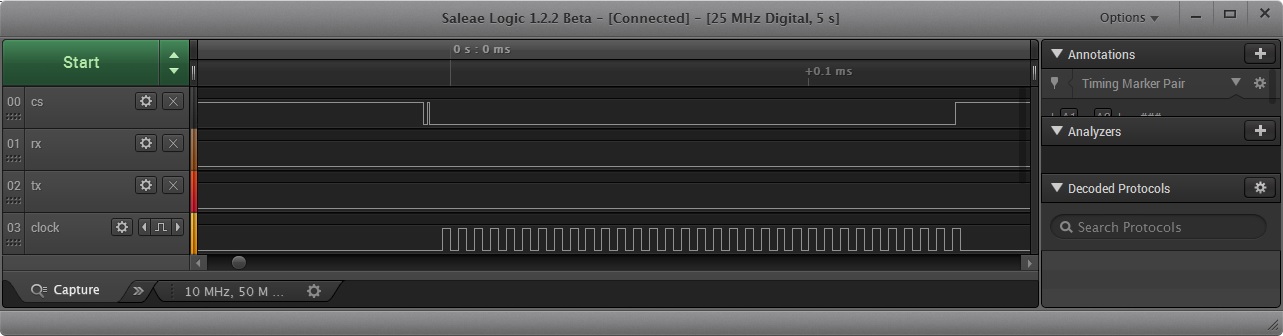
I have some problems with the SPI it seems. I suspect it's a  /CS signal problem. Flash command, Address and Datavector, needs to be read/written in one frame while /CS is contiguously low.

At the face of it writing the memories work (unverified!) but reading fails (at the comment below). Here is the code just a little simplified. SPI data width is set to 8-bits with SSIConfigSetExpClk()


    //  ******** erase the memory *********

    // wait while busy

    do {
        SSIDataPut(DISPLAYFLASH_SSI, WB_RD_STATUSREG1);
        SSIDataGet(DISPLAYFLASH_SSI, &status1);
    }
    while(status1 & 0x01);

    // erase the whole chip
    SSIDataPut(DISPLAYFLASH_SSI, WB_WREN);
    SSIDataPut(DISPLAYFLASH_SSI, WB_CHIP_ERASE);


    //  ******** write the memory *********

    SSIAdvModeSet(ssi_base, SSI_ADV_MODE_READ_WRITE);

    // wait while busy

    do {
        SSIDataPut(DISPLAYFLASH_SSI, WB_RD_STATUSREG1);
        SSIDataGet(DISPLAYFLASH_SSI, &status1);
    }
    while(status1 & 0x01);

    SSIAdvFrameHoldEnable(ssi_base);

    // write flash command

    SSIDataPut(DISPLAYFLASH_SSI, WB_WREN)
    SSIDataPut(DISPLAYFLASH_SSI, WB_PAGE_PRG);

    // write 24-bit address

    SSIDataPut(ssibase, addr1);
    SSIDataPut(ssibase, addr2);
    SSIDataPut(ssibase, addr3);

    // write data

    while(--putcount_minusone) {
        SSIDataPut(ssi_base, (uint32_t)*dptr8++);
    }
    SSIAdvDataPutFrameEnd(ssi_base, (uint32_t)*dptr8);

    SSIAdvFrameHoldDisable(ssi_base);
    SSIAdvModeSet(ssi_base, SSI_ADV_MODE_LEGACY);


    //  ******** read the memory *********

    SSIAdvModeSet(ssi_base, SSI_ADV_MODE_READ_WRITE);

    // wait while busy
    do {
        SSIDataPut(DISPLAYFLASH_SSI, WB_RD_STATUSREG1);
        SSIDataGet(DISPLAYFLASH_SSI, &status1);
    }
    while(status1 & 0x01);

    SSIAdvFrameHoldEnable(ssi_base);

    // write flash command

    SSIDataPut(DISPLAYFLASH_SSI, WB_RD);

    // write 24 bit address

    SSIDataPut(ssibase, addr1);
    SSIDataPut(ssibase, addr2);
    SSIDataPut(ssibase, addr3);

    // read data

    while(getcount--) {
        SSIDataGet(ssibase, &data32);    /* <------------ SSIDataGet() does not return (blocks) on the fifth loop count --------------- */
        *dptr8++ = (uint8_t)data32;
    }

    SSIAdvFrameHoldDisable(ssi_base);
    SSIAdvModeSet(ssi_base, SSI_ADV_MODE_LEGACY);

  • Hello Kim,

    How have you configured the SSI Module and the System? Could you please share the initialization code?

    Alternatively, you can check the following TI Design which uses SSI to communicate with an external serial flash

    www.ti.com/.../TIDM-TM4C129SDRAMNVM;amp

    Regards
    Amit
  • And - similar to another "SPI-based" post arriving here today -  this  appears to be a custom board.     Thus - is the routing/implementation between MCU and memories "proper?"    (i.e. short/direct traces - which avoid nearby noise sources)

    As always - KISS dictates that we start such interfaces at "low speed" - building methodically w/each success.   (such reduced signal speed overcomes/forgives a multitude of interconnect and/or layout "sins.")

  • Thanks. The SPI bus can be driven as master both by the TM4C129 and by PX8338QA.
    So theoretically that could be the problem, even if that "should" not happen before I release reset on the PX8338QA.
    However I have the same problem on other SPI buses.


    	/** Setup SSI2 on DISP_MEM -- writes PX8338QA graphics processor and its flash memory Winbond W25Q16DV */
    	/*
    	 * L	DISP_MEM			MCU		PX8338QA	W25Q16DV(GPU Flash)
    	 *
    	 * 0	SSI02_MISO			PD0		SPIRXD0		IRIS_SPIRXD0		SPI/RX/MISO
    	 * 1	SSI02_MOSI			PD1		SPITXD0		IRIS_SPITXD0		SPI/TX/MOSI
    	 * 2	SSI02_CS			PD2		SPICS0		IRIS_SPICS0		SPI/CS
    	 * 3	SSI02_CLK			PD3		SPICLK0		IRIS_SPICLKO		SPI/CLK
    	 * 4	DISPMEM_HOLD		PD4					MEM_HOLD		MEM/HOLD
    	 * 5	DISPMEM_WP			PD5					MEM_WP			MEM/WRITE_PROTECT
    	 */
    
    	SysCtlPeripheralEnable(SYSCTL_PERIPH_SSI2);
    	SysCtlPeripheralReset(SYSCTL_PERIPH_SSI2);
    
    	GPIOPinTypeGPIOOutput(GPIO_PORTD_BASE, GPIO_PIN_1 | GPIO_PIN_2 | GPIO_PIN_3); // TX, CS, CLK are set as output
    	GPIOPinTypeGPIOInput(GPIO_PORTD_BASE, GPIO_PIN_0); 	// RX is set as input
    
    	GPIOPinConfigure(GPIO_PD1_SSI2XDAT0);    // MOSI/TX line
    	GPIOPinConfigure(GPIO_PD0_SSI2XDAT1);    // MISO/RX line
    	GPIOPinConfigure(GPIO_PD2_SSI2FSS);
    	GPIOPinConfigure(GPIO_PD3_SSI2CLK);
    
    	GPIOPinTypeSSI(GPIO_PORTD_BASE, GPIO_PIN_0 | GPIO_PIN_1 | GPIO_PIN_2 | GPIO_PIN_3);
    
    	SSIClockSourceSet(SSI2_BASE, SSI_CLOCK_SYSTEM); // sets the system clock as the source of clock (redundant?)
    
    	while(SSIBusy(ssibase)); // wait while busy
    	SSIConfigSetExpClk(SSI2_BASE, SystemClock, SSI_FRF_MOTO_MODE_0, SSI_MODE_MASTER, SystemClock/2, 8);
    
    	SSIEnable(SSI2_BASE);
    
    	// empty FIFO, flush unwanted junk
    	while(SSIDataGetNonBlocking(SSI2_BASE, &flushfifo));
    

  • I think I cannot use the adv modes.
    SSIAdvModeSet(ssi_base, SSI_ADV_MODE_LEGACY), legacy mode seems to be the right mode, with rx, tx , cs and clk pins? But then I cannot use any other SSIAdv<X>() functions to control frame length and CS pin?

    How can I now define a frame?
    CS pin needs to be active during the whole frame without interruption:
    Writing command, writing address and reading or writing data.

    I tried to force the CS pin with GPIOPinWrite() but it did not work.
  • Hello Kim,

    I have a sample code to do so for the TM4C129x albeit on SSI3. You may want to use this as a reference. For the GPIOPinwrite to work the GPIO has to be configured as a GPIO Pin using GPIOPinTypeGPIOOutput and not as SSI FSS Pin.

    #include <stdlib.h>
    #include <stdint.h>
    #include <stdbool.h>
    #include "inc/hw_memmap.h"
    #include "inc/hw_types.h"
    #include "inc/hw_gpio.h"
    #include "inc/hw_ssi.h"
    #include "inc/hw_sysctl.h"
    #include "inc/hw_epi.h"
    #include "inc/hw_ints.h"
    #include "inc/hw_nvic.h"
    #include "inc/hw_uart.h"
    #include "driverlib/debug.h"
    #include "driverlib/fpu.h"
    #include "driverlib/gpio.h"
    #include "driverlib/rom.h"
    #include "driverlib/rom_map.h"
    #include "driverlib/interrupt.h"
    #include "driverlib/pin_map.h"
    #include "driverlib/sysctl.h"
    #include "driverlib/ssi.h"
    #include "driverlib/uart.h"
    #include "utils/uartstdio.h"
    
    #define NUM_SSI_DATA 				20
    #define INS_WRITE_ENABLE 			0x06
    #define INS_READ_STATUS_REGISTER1   0x05
    #define DUMMY_BYTE       			0x00
    #define FLASH_BUSY_BIT				0x01
    #define FLASH_WRITE_EN_LATCH_BIT	0x02
    #define INS_SECTOR_ERASE_4KB 		0x20
    #define INS_PAGE_PROGRAM   			0x02
    #define INS_READ_DATA   			0x03
    
    
    uint8_t g_ui8InstrReadID[] = {0x90,0x00,0x00,0x00};
    uint32_t pui32DataTx[NUM_SSI_DATA];
    uint32_t pui32DataRx[NUM_SSI_DATA];
    
    //*****************************************************************************
    //
    // This function sets up SSI External Flash ID Read
    //
    //*****************************************************************************
    uint32_t SSILibSendReadIDAdvMode(uint32_t ui32Base)
    {
       uint32_t ui32Idx, ui32Receive;
       uint32_t ui32MfgID;
       uint32_t ui32DevID;
       uint32_t ui32ReadID[]={0xaa,0xaa};
       uint32_t ui32ReadIDFlash;
    
       for(ui32Idx = 0; ui32Idx < sizeof(g_ui8InstrReadID) / sizeof(g_ui8InstrReadID[0]); ui32Idx++)
       {
         SSIDataPut(ui32Base, g_ui8InstrReadID[ui32Idx]);
       }
    
       SSIAdvModeSet(ui32Base,SSI_ADV_MODE_READ_WRITE);
       SSIDataPut(ui32Base, 0x00);
       SSIDataGet(ui32Base, &ui32Receive);
       ui32ReadID[0] = ui32Receive;
       SSIAdvDataPutFrameEnd(ui32Base,0x00);
       SSIDataGet(ui32Base, &ui32Receive);
       ui32ReadID[1] = ui32Receive;
       ui32MfgID = ui32ReadID[0];
       ui32DevID = ui32ReadID[1];
       ui32ReadIDFlash = ui32MfgID;
    
       ui32ReadIDFlash = ui32ReadIDFlash << 8;
       ui32ReadIDFlash |= ui32DevID;
    
       SSIAdvModeSet(SSI3_BASE,SSI_ADV_MODE_WRITE);
    
       return ui32ReadIDFlash;
    }
    
    uint8_t
    SSILibSendReadStatusRegister(uint32_t ui32Base, uint8_t ui8FlashCommand)
    {
        uint32_t ui32Status = 0;
        uint8_t ui8FlashStatus;
    
        SSIAdvFrameHoldEnable(ui32Base);
        SSIDataPut(ui32Base,ui8FlashCommand);
        SSIAdvModeSet(ui32Base,SSI_ADV_MODE_READ_WRITE);
        SSIAdvDataPutFrameEnd(ui32Base,DUMMY_BYTE);
        while(SSIBusy(ui32Base));
        SSIDataGet(ui32Base, &ui32Status);
        ui8FlashStatus = (uint8_t)ui32Status;
        SSIAdvModeSet(SSI3_BASE,SSI_ADV_MODE_WRITE);
    
        return ui8FlashStatus;
    }
    
    
    void
    SSILibDeviceBusyCheck(uint32_t ui32Base)
    {
       uint8_t ui8TempData=0xFF;
    
       ui8TempData = SSILibSendReadStatusRegister(ui32Base,INS_READ_STATUS_REGISTER1);
    
       while((ui8TempData & FLASH_BUSY_BIT) == FLASH_BUSY_BIT)
       {
          ui8TempData = SSILibSendReadStatusRegister(ui32Base,INS_READ_STATUS_REGISTER1);
       }
    }
    
    void
    SSILibSendPageProgram(uint32_t ui32Base, uint32_t ui32Address, uint8_t ui8FlashCommand)
    {
        uint32_t ui32TempAddr, ui32TempData;
        uint8_t ui8AddrByte1, ui8AddrByte2, ui8AddrByte3;
    
        ui32TempAddr = ui32Address >> 16 ;
        ui8AddrByte1 = (uint8_t)ui32TempAddr;
        ui32TempAddr = ui32Address >> 8 ;
        ui8AddrByte2 = (uint8_t)ui32TempAddr;
        ui8AddrByte3 = (uint8_t)ui32Address;
    
        SSIAdvModeSet(SSI3_BASE,SSI_ADV_MODE_WRITE);
        SSIAdvFrameHoldEnable(ui32Base);
        SSIAdvDataPutFrameEnd(ui32Base,INS_WRITE_ENABLE);
        while(SSIBusy(ui32Base));
    
        ui32TempData = SSILibSendReadStatusRegister(ui32Base,INS_READ_STATUS_REGISTER1);
        while((ui32TempData & FLASH_WRITE_EN_LATCH_BIT) != FLASH_WRITE_EN_LATCH_BIT) {
          ui32TempData = SSILibSendReadStatusRegister(ui32Base,INS_READ_STATUS_REGISTER1);
        }
    
        SSIAdvModeSet(SSI3_BASE,SSI_ADV_MODE_WRITE);
        SSIAdvFrameHoldEnable(ui32Base);
        SSIDataPut(ui32Base,ui8FlashCommand);
        SSIDataPut(ui32Base,ui8AddrByte1);
        SSIDataPut(ui32Base,ui8AddrByte2);
        SSIDataPut(ui32Base,ui8AddrByte3);
    }
    
    void
    SSILibSendReadDataAdvBi(uint32_t ui32Base, uint32_t ui32Address, uint8_t ui8FlashCommand)
    {
        uint32_t ui32TempAddr;
        uint8_t ui8AddrByte1, ui8AddrByte2, ui8AddrByte3;
    
        ui32TempAddr = ui32Address >> 16 ;
        ui8AddrByte1 = (uint8_t)ui32TempAddr;
        ui32TempAddr = ui32Address >> 8 ;
        ui8AddrByte2 = (uint8_t)ui32TempAddr;
        ui8AddrByte3 = (uint8_t)ui32Address;
        SSIAdvModeSet(SSI3_BASE,SSI_ADV_MODE_WRITE);
        SSIAdvFrameHoldEnable(ui32Base);
        SSIDataPut(ui32Base,ui8FlashCommand);
        SSIDataPut(ui32Base,ui8AddrByte1);
        SSIDataPut(ui32Base,ui8AddrByte2);
        SSIDataPut(ui32Base,ui8AddrByte3);
    
        SSIAdvModeSet(ui32Base,SSI_ADV_MODE_READ_WRITE);
    }
    
    
    //*****************************************************************************
    //
    // This function sets up SSI External Flash Erase
    //
    //*****************************************************************************
    void
    SSILibSendEraseCommand (uint32_t ui32Base, uint32_t ui32Address, uint8_t ui8FlashCommand)
    {
        uint32_t ui32TempAddr, ui32TempData;
        uint8_t ui8AddrByte1, ui8AddrByte2, ui8AddrByte3;
    
        ui32TempAddr = ui32Address >> 16 ;
    
        ui8AddrByte1 = (uint8_t)ui32TempAddr;
        ui32TempAddr = ui32Address >> 8 ;
        ui8AddrByte2 = (uint8_t)ui32TempAddr;
        ui8AddrByte3 = (uint8_t)ui32Address;
    
        SSIAdvModeSet(SSI3_BASE,SSI_ADV_MODE_WRITE);
        SSIAdvFrameHoldEnable(ui32Base);
        SSIAdvDataPutFrameEnd(ui32Base,INS_WRITE_ENABLE);
        while(SSIBusy(ui32Base));
    
        ui32TempData = SSILibSendReadStatusRegister(ui32Base,INS_READ_STATUS_REGISTER1);
        while((ui32TempData & FLASH_WRITE_EN_LATCH_BIT) != FLASH_WRITE_EN_LATCH_BIT) {
          ui32TempData = SSILibSendReadStatusRegister(ui32Base,INS_READ_STATUS_REGISTER1);
        }
    
        SSIAdvModeSet(SSI3_BASE,SSI_ADV_MODE_WRITE);
        SSIAdvFrameHoldEnable(ui32Base);
        SSIDataPut(ui32Base,ui8FlashCommand);
        SSIDataPut(ui32Base,ui8AddrByte1);
        SSIDataPut(ui32Base,ui8AddrByte2);
        SSIAdvDataPutFrameEnd(ui32Base,ui8AddrByte3);
        while(SSIBusy(ui32Base));
        //wait till the erase is completed
        SSILibDeviceBusyCheck(ui32Base);
    
    }
    
    //*****************************************************************************
    //
    // This function sets up UART0 to be used for a console to display information
    // as the example is running.
    //
    //*****************************************************************************
    void
    InitConsole(void)
    {
        //
        // Enable GPIO port A which is used for UART0 pins.
        // TODO: change this to whichever GPIO port you are using.
        //
        SysCtlPeripheralEnable(SYSCTL_PERIPH_GPIOA);
    
        //
        // Configure the pin muxing for UART0 functions on port A0 and A1.
        // This step is not necessary if your part does not support pin muxing.
        // TODO: change this to select the port/pin you are using.
        //
        GPIOPinConfigure(GPIO_PA0_U0RX);
        GPIOPinConfigure(GPIO_PA1_U0TX);
    
        //
        // Enable UART0 so that we can configure the clock.
        //
        SysCtlPeripheralEnable(SYSCTL_PERIPH_UART0);
    
        //
        // Use the internal 16MHz oscillator as the UART clock source.
        //
        UARTClockSourceSet(UART0_BASE, UART_CLOCK_PIOSC);
    
        //
        // Select the alternate (UART) function for these pins.
        // TODO: change this to select the port/pin you are using.
        //
        GPIOPinTypeUART(GPIO_PORTA_BASE, GPIO_PIN_0 | GPIO_PIN_1);
    
        //
        // Initialize the UART for console I/O.
        //
        UARTStdioConfig(0, 115200, 16000000);
    }
    
    //*****************************************************************************
    //
    // Configure SSI3 in master Freescale (SPI) mode.  This example will send out
    // 3 bytes of data, then wait for 3 bytes of data to come in.  This will all be
    // done using the polling method.
    //
    //*****************************************************************************
    int
    main(void)
    {
        uint32_t pui32Dummy[1];
        uint32_t ui32Index;
        uint32_t ui32DeviceID;
        uint32_t ui32SysClockFreq;
    
        //
        // Set the clocking to run directly from the external crystal/oscillator.
        // TODO: The SYSCTL_XTAL_ value must be changed to match the value of the
        // crystal on your board.
        //
        ui32SysClockFreq = SysCtlClockFreqSet((SYSCTL_XTAL_25MHZ |
                                               SYSCTL_OSC_MAIN |
                                               SYSCTL_USE_PLL |
                                               SYSCTL_CFG_VCO_480), 120000000);
        //
        // Set up the serial console to use for displaying messages.  This is
        // just for this example program and is not needed for SSI operation.
        //
        InitConsole();
    
        //
        // Display the setup on the console.
        //
        UARTprintf("SSI3 To DK-TM4C129 FLASH TRANSFER\n");
    
        //
        // The SSI3 peripheral must be enabled for use.
        //
        SysCtlPeripheralEnable(SYSCTL_PERIPH_SSI3);
    
        //
        // For this example SSI3 is used with PortA[5:2].  The actual port and pins
        // used may be different on your part, consult the data sheet for more
        // information.  GPIO port A needs to be enabled so these pins can be used.
        // TODO: change this to whichever GPIO port you are using.
        //
        SysCtlPeripheralEnable(SYSCTL_PERIPH_GPIOQ);
        SysCtlPeripheralEnable(SYSCTL_PERIPH_GPIOF);
        SysCtlPeripheralEnable(SYSCTL_PERIPH_GPIOA);
    
        //
        // GPIO Port F0 Pin is Locked. So Unlock and write the CR bit
        //
        HWREG(GPIO_PORTF_BASE+GPIO_O_LOCK) = GPIO_LOCK_KEY;
        HWREG(GPIO_PORTF_BASE+GPIO_O_CR)   |= GPIO_PIN_0;
    
        //
        // Configure the pin muxing for SSI3 functions on port Q0, Q1, Q2, F0,
        // F4, F5
        //
        GPIOPinConfigure(GPIO_PQ0_SSI3CLK);
        GPIOPinConfigure(GPIO_PQ1_SSI3FSS);
        GPIOPinConfigure(GPIO_PQ2_SSI3XDAT0);
        GPIOPinConfigure(GPIO_PF0_SSI3XDAT1);
        GPIOPinConfigure(GPIO_PF4_SSI3XDAT2);
        GPIOPinConfigure(GPIO_PF5_SSI3XDAT3);
    
        //
        // Configure the GPIO settings for the SSI pins.  This function also gives
        // control of these pins to the SSI hardware.  Consult the data sheet to
        // see which functions are allocated per pin.
        // The pins are assigned as follows:
        //      PF5 - SSI3XDAT3
        //      PF4 - SSI3XDAT2
        //      PF0 - SSI3XDAT1
        //      PQ2 - SSI3XDAT0
        //      PQ1 - SSI3Fss
        //      PQ0 - SSI3CLK
        // TODO: change this to select the port/pin you are using.
        //
        GPIOPinTypeSSI(GPIO_PORTQ_BASE, GPIO_PIN_2 | GPIO_PIN_1 |
                       GPIO_PIN_0);
        GPIOPinTypeSSI(GPIO_PORTF_BASE, GPIO_PIN_5 | GPIO_PIN_4 |
                       GPIO_PIN_0);
    
        //
        // Configure and enable the SSI port for SPI master mode.  Use SSI3,
        // system clock supply, idle clock level low and active low clock in
        // freescale SPI mode, master mode, 1MHz SSI frequency, and 8-bit data.
        // For SPI mode, you can set the polarity of the SSI clock when the SSI
        // unit is idle.  You can also configure what clock edge you want to
        // capture data on.  Please reference the datasheet for more information on
        // the different SPI modes.
        //
        SSIConfigSetExpClk(SSI3_BASE, ui32SysClockFreq, SSI_FRF_MOTO_MODE_0,
                           SSI_MODE_MASTER, 1000000, 8);
    
        //
        // Enable the SSI3 module.
        //
        SSIAdvModeSet(SSI3_BASE,SSI_ADV_MODE_WRITE);
        SSIAdvFrameHoldEnable(SSI3_BASE);
        SSIEnable(SSI3_BASE);
    
        //
        // Read any residual data from the SSI port.  This makes sure the receive
        // FIFOs are empty, so we don't read any unwanted junk.  This is done here
        // because the SPI SSI mode is full-duplex, which allows you to send and
        // receive at the same time.  The SSIDataGetNonBlocking function returns
        // "true" when data was returned, and "false" when no data was returned.
        // The "non-blocking" function checks if there is any data in the receive
        // FIFO and does not "hang" if there isn't.
        //
        while(SSIDataGetNonBlocking(SSI3_BASE, &pui32Dummy[0]))
        {
        }
    
        //
        // Initialize the Transmit Buffer
        //
        for(ui32Index=0;ui32Index<NUM_SSI_DATA;ui32Index++)
        {
        	pui32DataTx[ui32Index] = rand()%256;
        	pui32DataRx[ui32Index] = 0x0;
        }
    
        //
        // First Read the DEVICE ID
        //
        ui32DeviceID = SSILibSendReadIDAdvMode(SSI3_BASE);
        if(ui32DeviceID != 0xC219)
        {
           	UARTprintf("No External Flash... Read Back %x\n",ui32DeviceID);
        	while(1);
        }
    
       	UARTprintf("External Flash Detected with Device ID %x\n",ui32DeviceID);
    
       	//
       	// Erase the Sector before Program Operation...
       	//
       	UARTprintf("Starting Erase Operations...\n");
       	SSILibSendEraseCommand(SSI3_BASE,0x0,INS_SECTOR_ERASE_4KB);
       	UARTprintf("Erase Completed...\n");
    
       	//
       	// Write NUM_SSI_DATA words to the External Flash
       	//
       	UARTprintf("Starting Program Operations...\n");
       	SSILibSendPageProgram(SSI3_BASE,0x0,INS_PAGE_PROGRAM);
        for(ui32Index=0;ui32Index<NUM_SSI_DATA-1;ui32Index++)
        {
        	SSIDataPut(SSI3_BASE,pui32DataTx[ui32Index]);
        }
        SSIAdvDataPutFrameEnd(SSI3_BASE,pui32DataTx[NUM_SSI_DATA-1]);
       	UARTprintf("Program Completed...\n");
    
       	//
       	// Read NUM_SSI_DATA words from the External Flash
       	//
       	UARTprintf("Starting Read Operations...\n");
       	SSILibSendReadDataAdvBi(SSI3_BASE,0x0,INS_READ_DATA);
        for(ui32Index=0;ui32Index<NUM_SSI_DATA-1;ui32Index++)
        {
            SSIDataPut(SSI3_BASE,DUMMY_BYTE);
            SSIDataGet(SSI3_BASE,&pui32DataRx[ui32Index]);
        }
        SSIAdvDataPutFrameEnd(SSI3_BASE,DUMMY_BYTE);
        SSIDataGet(SSI3_BASE,&pui32DataRx[NUM_SSI_DATA-1]);
       	UARTprintf("Read Completed...\n");
    
       	//
       	// Display Data
       	//
        for(ui32Index=0;ui32Index<NUM_SSI_DATA;ui32Index++)
        {
        	UARTprintf("Program: %x Read: %x\n",pui32DataTx[ui32Index],pui32DataRx[ui32Index]);
        }
    
        while(1);
    
    }
    

    Regards

    Amit

  • Hi Amit,

    Would it not prove immensely helpful - to most all here - if these "sample codes" were better (i.e. somewhat) publicized/promoted - so that many could first FIND THEM - and thus BENEFIT?    Methods of "release" - as demonstrated here - are "hit/miss" (thus extremely limiting) are they not?

    There MUST be a "better way!"

  • Hello cb1,

    The example code was already marked out in my first reply (The TI Design has these released)....

    Regards
    Amit
  • Yes - but poster - and I - missed that!

    Where is this "TI Design" - how, when, where has it been promoted? I'm here (fairly) regularly (some would say - "too much") and I DO NOT KNOW! (and I doubt that I'm alone!)

    Obscuring valuable data (much of it your unique creation) makes NO Sense to me/my group - cannot a better way be found?
  • Hello cb1,

    So field is promoting the new TI Designs and I have updated the forum thread (that lost it sticky status) when the 2 designs came out. Any ideas, if poster only posts w/o looking into resources?

    Regards
    Amit
  • Amit Ashara said:
    Any ideas

    Hi Amit,

    Though that you'd, "Never ask!"

    Why Yes - I've an "idea."   I honestly have only the "slightest" knowledge of, "TI Designs."    Understand that as small biz owner we work w/many vendors - not just one - and our ability to, "EFFICIENTLY FIND and EXPLOIT SUCH CRITICAL TECH INFORMATION IS MANDATORY!"   And presently - we cannot do that, here! 

    That's our need - and I expect that of many - too.   

    As to an "idea" - a broad, bright red stripe runs atop the forum - lists: Support, Blogs, Groups, Video.   And not one word re, "Critical Tech Data for these MCUs!"

    Would not that be a, "Prime Location" for all here to "initiate" their, "TECH DATA SEARCH?"  

    Seriously - are Blogs, Groups, Videos more important than the, "Eased, Speeded & Enhanced LOCATION OF VITAL MCU TECH DATA?" 

  • Hello cb1

    I always ask when I believe I am not the right candidate for the answer. Thanks, point taken but how many would look at the "Red Stripe" other than you, me and some valuable forum folks...I think we can take this offline.

    Regards
    Amit
  • I'm working in the same project as Kim does. I wonder if there is something wrong with the used method to initialize the SPI bus? The initialization code is provided here as is, I only concatenated code which initializes four different peripheral chips pins. The logic is same for all chips, only pins and ports are different.

    The problem is same as before, writing firmware to flash works (at least not hangs) but reading does not. However, I'm not convinced if writing works either because when reading from chip, I get only zero (or null) back. In top of that, reading function get stuck always after 8 blocks.

    The code is in other part same as before (in first post) but SSIAdvMode is no longer used. That is replaced with self written code which writes the value for CS pin manually to control frame length.

    /* Basic setup of pins */
    
    GPIOPinTypeGPIOOutput(GPIO_PORTA_BASE, GPIO_PIN_6);
    GPIOPinTypeGPIOInput(GPIO_PORTA_BASE, GPIO_PIN_7);
    GPIOPinWrite(GPIO_PORTA_BASE, GPIO_PIN_6, 0);
    
    GPIOPinTypeGPIOOutput(GPIO_PORTD_BASE, GPIO_PIN_4 | GPIO_PIN_5);
    GPIOPinWrite(GPIO_PORTD_BASE, GPIO_PIN_4 | GPIO_PIN_5, 0 | GPIO_PIN_5);
    
    GPIOPinTypeGPIOOutput(GPIO_PORTP_BASE, GPIO_PIN_0 | GPIO_PIN_1);
    GPIOPinWrite(GPIO_PORTP_BASE, GPIO_PIN_0 | GPIO_PIN_1, GPIO_PIN_0 | GPIO_PIN_1);
    
    GPIOPinTypeGPIOOutput(GPIO_PORTP_BASE, GPIO_PIN_2 | GPIO_PIN_3);
    GPIOPinWrite(GPIO_PORTP_BASE, GPIO_PIN_2 | GPIO_PIN_3, GPIO_PIN_2 | GPIO_PIN_3);
    
    
    /* SPI setup */
    
    uint32_t flushfifo;
    
    SysCtlPeripheralEnable(SYSCTL_PERIPH_SSI0);
    
    GPIOPinConfigure(GPIO_PA4_SSI0XDAT0);    // MOSI/TX line
    GPIOPinConfigure(GPIO_PA5_SSI0XDAT1);    // MISO/RX line
    GPIOPinConfigure(GPIO_PA3_SSI0FSS);
    GPIOPinConfigure(GPIO_PA2_SSI0CLK);
    
    GPIOPinTypeSSI(GPIO_PORTA_BASE, GPIO_PIN_2 | GPIO_PIN_4 | GPIO_PIN_5 );
    GPIOPinTypeGPIOOutput(GPIO_PORTA_BASE, GPIO_PIN_3); // CS is set as output
    
    GPIOPinWrite(GPIO_PORTA_BASE, GPIO_PIN_3, GPIO_PIN_3);
    
    SSIClockSourceSet(SSI0_BASE, SSI_CLOCK_SYSTEM);
    spi_width(SSI0_BASE, DEFAULT_SSIWIDTH);
    
    SysCtlPeripheralReset(SYSCTL_PERIPH_SSI0);
    SSIEnable(SSI0_BASE);
    
    // empty FIFO, flush unwanted junk
    while(SSIDataGetNonBlocking(SSI0_BASE, &flushfifo));
    // do the same for 3 other peripheral chips
    
    /* spi width function */
    
    while(SSIBusy(ssibase));
    SSIConfigSetExpClk(ssibase, SystemClock, SSI_FRF_MOTO_MODE_0,
    	                       SSI_MODE_MASTER, SystemClock/256, 8);      // Tried with very slow speed, still hangs

  • Hello Pauli,

    The following must be done

    Pauli Korhonen said:
    SSIEnable(SSI0_BASE); // empty FIFO, flush unwanted junk while(SSIDataGetNonBlocking(SSI0_BASE, &flushfifo)); // do the same for 3 other peripheral chips

    after

    Pauli Korhonen said:
    SSIConfigSetExpClk(ssibase, SystemClock, SSI_FRF_MOTO_MODE_0, SSI_MODE_MASTER, SystemClock/256, 8);

    The advanced modes do work as expected with serial flash memory. Did you check the example project?

    Regards

    Amit

  • Thank you for your answer. I've read the example project but I just wanted to make sure that CS stays down during whole frame hence the manual handling.

    Maybe my code snippet is not very clear on that but the order of commands is in fact same as in your answer. If you check again, "spi_width" is a function and it is called before SSIEnable. Maybe I should wrote spi_width to look like function, instead of just comment it as such, to avoid confusion...

  • I tested this code with logic analyzer and the problem seems to be that CS gets high before write has completed. Please see attached picture. I can't connect CS pin to SSI module because I later need to keep CS low during whole frame.

    static void gpu_wait_flash_busy(void)
     {
    	uint32_t status1;		//< Status register value
    
    	// wait while busy status
    
    	GPIOPinWrite(GPIO_PORTD_BASE, GPIO_PIN_2, 0); // CS low -- activated
    	SSIDataPut(DISPLAYFLASH_SSI, WB_RD_STATUSREG1);
    
            // TODO  ****************** wait here until SSIDataPut is ready *************************
    
    	GPIOPinWrite(GPIO_PORTD_BASE, GPIO_PIN_2, GPIO_PIN_2); // CS high -- deactivated
    
    	GPIOPinWrite(GPIO_PORTD_BASE, GPIO_PIN_2, 0); // CS low --  activated
    	do {
    
    		SSIDataGet(DISPLAYFLASH_SSI, &status1);
    	}
    	while (status1 & 0x01);
    
    	GPIOPinWrite(GPIO_PORTD_BASE, GPIO_PIN_2, GPIO_PIN_2); // CS high -- deactivated
    }

  • Hello Pauli,

    First of all the Advanced Modes do that where they manage the CS as per the user transmission.

    Second of all in the legacy mode (which is what you are using), after a SSIDataPut you need to wait for SSIBusy to be deasserted and then read the data from the SSI RX FIFO using SSIDataGet to flush the data received. Then when you poll again, you need to put Data to get Data.

    GPIOPinWrite(GPIO_PORTD_BASE, GPIO_PIN_2, 0); // CS low -- activated
    SSIDataPut(DISPLAYFLASH_SSI, WB_RD_STATUSREG1);

    while(SSIBusy(DISPLAYFLASH_SSI));
    SSIDataGet(DISPLAYFLASH_SSI, &status1);

    GPIOPinWrite(GPIO_PORTD_BASE, GPIO_PIN_2, GPIO_PIN_2); // CS high -- deactivated

    GPIOPinWrite(GPIO_PORTD_BASE, GPIO_PIN_2, 0); // CS low -- activated
    do {
    SSIDataPut(DISPLAYFLASH_SSI, 0x0);
    SSIDataGet(DISPLAYFLASH_SSI, &status1);
    }
    while (status1 & 0x01);

    GPIOPinWrite(GPIO_PORTD_BASE, GPIO_PIN_2, GPIO_PIN_2); // CS high -- deactivated

    Regards
    Amit