This thread has been locked.

If you have a related question, please click the "Ask a related question" button in the top right corner. The newly created question will be automatically linked to this question.

MPU9150 Example Error Arbitration Lost

I'm trying to get my hands on the MPU9150 9-axis motion sensor using TM4C123G. I imported the compdcm_mpu9150 example project but ends up with some problems. After I2C initialization and before MPU9150 initialization, the serial monitor (consistently) displays an error message:

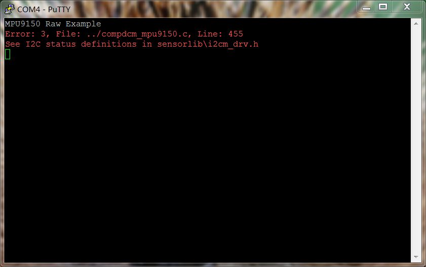
I searched and found the error3 to be I2CM_STATUS_ARB_LOST - master arbitration lost. I have been reading about possible causes of I2C arbitration lost, some of the reasons being that the slave is pulling the SDA low so that master could not initiate a new transfer. One of the most common solution is to toggle the SCL and eventually the slave will release SDA. In an attempt to solve the problem, I added the following code segment before MPU9150Init (MPU9150Init is where the I2C line hang): (PD0-SCL, PD1-SDA, PB5-used for measuring logic level of SDA)

uint_fast8_t sdaVal = GPIOPinRead(GPIO_PORTB_BASE, GPIO_PIN_5); // initial check the sda
    if (sdaVal == 0){
    	while(sdaVal == 0) {
    		GPIOPinWrite(GPIO_PORTD_BASE, GPIO_PIN_0, 0); // write 0 to scl
    		SysCtlDelay(500); // wait after lower edge
    		sdaVal = GPIOPinRead(GPIO_PORTB_BASE, GPIO_PIN_5);
    		UARTprintf("SDA %d", sdaVal);
    		if (sdaVal != 0) {
    			break;
    		}
    		else {
    			GPIOPinWrite(GPIO_PORTD_BASE, GPIO_PIN_0, GPIO_PIN_0); // write 1 to scl
    			SysCtlDelay(500); // wait after lower edge
    			sdaVal = GPIOPinRead(GPIO_PORTB_BASE, GPIO_PIN_5);
    			UARTprintf("SDA %d", sdaVal);
    			if (sdaVal != 0) {
    				break;
    			}
    		}
    		if (sdaVal != 0) {
    			break;
    		}
    	}
    }

As you could see, I was trying to toggle SCL, and monitor SDA after every toggle hoping it could be released by the slave. However, the slave does not release SDA after a lot of toggles, and the SDA remains low. 

I'm not sure whether I made any mistakes in trying to solve the problem or it's actually due to some other reasons. And I'm a little surprised the the example project won't work on the exact sensor. (I'm using CCS V6 and newest TIVAWARE, I also tried CCSV5, reinstall TIVAWARE and ended up futile, this problem persists).

Any ideas?

  • Hello Bill,

    Can you enable the Pull Up on the SCL and SDA GPIO's and then see if it works. I presume that the external pull up is not working.

    Regards
    Amit
  • Hello Amit,

    Thank you for your answer. There might be something I did not explain cleary in my question. The SCL pull up is working fine when I measured it after initialization and the DMM reading showns 3.3v, somehow the SDA remains low all the time. I have tested the I2C slave on other microcontrollers and it works perfectly, which means there might not be a defect with the pull up I2C slave (sensor). Could this evidence confirm that the pull ups on the slave is actually working?

    Thanks,
    Bill
  • May I intrude and (perhaps w/luck) assist?    Would not the (temporary) addition of an external pull-up @ SDA eliminate that as an issue?   To my mind - that's the best, "real-world" test.

    While you've tested the I2C slave w/other MCUs - and it works - surely there are (some) changes caused by such "movement."   For instance - unstated is how & when you power & interconnect your I2C slave.   If "stealing" power from an LPad - might that extra current drain be "just sufficient" to confound the slave?   And the cabling between the two - have you (really) "ohmed out" SCL - from MCU to the Slave?   (NOT just to board headers!)

    If there's even the most remote chance that a, "missing, improper" pull-up R is present - such is a very quick/easy "fix."

    If my firm had a "nickel" for each time clients' "swore" they did this (and had not!)...   (and of course we charged them for the "pleasure" of our company...)

  • Hello cb1,

    Thank you very much for your suggestion. However, after I tried to connect an external 3.3v pull up to the SDA, problem seem to remain. But you inspired me to do another experiment - (without the 3.3v external pull up) unplugging the SDA line connected to the master when the error occured, the voltage on the slave SDA changed to 3.3v! which means the slave has proper pull ups and master is somehow draining line low.

    Following this observation, I did a series of measurements using a DMM at different part of the program:

    Connection between the master and slave (SDA/SCL)

    Connected Connected Disconnected Disconnected Disconnected Disconnected Code
    SCL SDA Master SCL Master SDA Slave SCL Slave SDA
    Before the program starts running 3.3v 0v 1.35v 0v 3.3v 3.3v
    After Pinmux Configuration 3.3v 0v 1.24v 0v 3.3v 3.3v ROM_GPIOPinConfigure(GPIO_PD0_I2C3SCL);
        ROM_GPIOPinConfigure(GPIO_PD1_I2C3SDA);
    After selecting I2C function 3.3v 0v 1.40v 0v 3.3v 3.3v GPIOPinTypeI2CSCL(GPIO_PORTD_BASE, GPIO_PIN_0);
        ROM_GPIOPinTypeI2C(GPIO_PORTD_BASE, GPIO_PIN_1);
    After I2C initialization 3.3v 0v 1.20v 0v 3.3v 3.3v I2CMInit(&g_sI2CInst, I2C3_BASE, INT_I2C3, 0xff, 0xff, ROM_SysCtlClockGet());
    After MPU9150 Initialization (when the error occurs) 3.3v 0v 1.30v 0v 3.3v 3.3v MPU9150Init(&g_sMPU9150Inst, &g_sI2CInst, MPU9150_I2C_ADDRESS,
                    MPU9150AppCallback, &g_sMPU9150Inst);


    My understanding of the above result is:

    The master SCL is pulled up weakly and master SDA is not. So that master SDA drains up the SDA line. However, I thought that the ROM_GPIOPinTypeI2C(GPIO_PORTD_BASE, GPIO_PIN_1) line would have already set the SDA to open-drain with a weak pull-up (though I'm not fully sure whether that's the case)

    Does the above observation give you any clue what is wrong with my set up? Thank you!


    Following is my complete code for the set up of I2C (after which the error occurs):

        //
        // Enable port B used for motion interrupt.
        //
        ROM_SysCtlPeripheralEnable(SYSCTL_PERIPH_GPIOB);
    
        //
        // The I2C3 peripheral must be enabled before use.
        //
        ROM_SysCtlPeripheralEnable(SYSCTL_PERIPH_I2C3);
        ROM_SysCtlPeripheralEnable(SYSCTL_PERIPH_GPIOD);
    
        //
        // Configure the pin muxing for I2C3 functions on port D0 and D1.
        //
        ROM_GPIOPinConfigure(GPIO_PD0_I2C3SCL);
        ROM_GPIOPinConfigure(GPIO_PD1_I2C3SDA);
    
        //
        // Select the I2C function for these pins.  This function will also
        // configure the GPIO pins pins for I2C operation, setting them to
        // open-drain operation with weak pull-ups.  Consult the data sheet
        // to see which functions are allocated per pin.
        //
        GPIOPinTypeI2CSCL(GPIO_PORTD_BASE, GPIO_PIN_0);
        ROM_GPIOPinTypeI2C(GPIO_PORTD_BASE, GPIO_PIN_1);
    
        //
        // Configure and Enable the GPIO interrupt. Used for INT signal from the
        // MPU9150
        //
        ROM_GPIOPinTypeGPIOInput(GPIO_PORTB_BASE, GPIO_PIN_2);
        GPIOIntEnable(GPIO_PORTB_BASE, GPIO_PIN_2);
        ROM_GPIOIntTypeSet(GPIO_PORTB_BASE, GPIO_PIN_2, GPIO_FALLING_EDGE);
        ROM_IntEnable(INT_GPIOB);
    
        //
        // Keep only some parts of the systems running while in sleep mode.
        // GPIOB is for the MPU9150 interrupt pin.
        // UART0 is the virtual serial port
        // TIMER0, TIMER1 and WTIMER5 are used by the RGB driver
        // I2C3 is the I2C interface to the ISL29023
        //
        ROM_SysCtlPeripheralClockGating(true);
        ROM_SysCtlPeripheralSleepEnable(SYSCTL_PERIPH_GPIOB);
        ROM_SysCtlPeripheralSleepEnable(SYSCTL_PERIPH_UART0);
        ROM_SysCtlPeripheralSleepEnable(SYSCTL_PERIPH_TIMER0);
        ROM_SysCtlPeripheralSleepEnable(SYSCTL_PERIPH_TIMER1);
        ROM_SysCtlPeripheralSleepEnable(SYSCTL_PERIPH_I2C3);
        ROM_SysCtlPeripheralSleepEnable(SYSCTL_PERIPH_WTIMER5);
    
        //
        // Enable interrupts to the processor.
        //
        ROM_IntMasterEnable();
    
        //
        // Initialize I2C3 peripheral.
        //
        I2CMInit(&g_sI2CInst, I2C3_BASE, INT_I2C3, 0xff, 0xff,
                 ROM_SysCtlClockGet());
    
        //
        // Initialize the MPU9150 Driver.
        //
        MPU9150Init(&g_sMPU9150Inst, &g_sI2CInst, MPU9150_I2C_ADDRESS,
                    MPU9150AppCallback, &g_sMPU9150Inst);

  • I'm on a jet w/in hours - glad you "dug deeper." I missed - or you did not clearly detail the value of (external) pull-up Rs. I do NOT recommend use of the MCU's "weak/enfeebled" pull-ups. (Yes - sometimes they'll work - and sometimes (w/my eyes closed) I'll return Nadal's serve!)

    The newer I2C protocol is bit of a "game changer" - cannot you "dial down" and insure that "OLD" style I2C - where open-drain ruled - is the ONLY one you use for now. (during this diagnostic phase) I know nothing of vendor's 129 device - we employ others in the 200MHz class - and also require M0, M3 & M7 - so 129 is "out."

  • Hello Bill,

    Can I suggest adding the following line before enabling I2C3

    ROM_SysCtlPeripheralReset(SYSCTL_PERIPH_I2C3);

    Regards
    Amit
  • Hello Amit,

    Thank you for your suggestion. Upon trying your suggestion and doing a few more experiment, I found the intrinsic problem, the PD1 port on my launch pad does not seem to work properly - it drains the 3.3v pull up and refuse to be pulled up even if I enable a pull up on that pin.

    After switching to I2C2 module, both SDA and SCL lines are pulled up properly now. Thank you for your effort in helping me resolve this problem.

    Somehow, I'm having a new problem now, still, on the MPU9150Init step, the program goes into an IntDefaultHandler and is trapped. I have no clue what kind of error leads to IntDefaultHandler, and the serial monitor shows nothing.

    Could you give me some ideas?

    Thanks so much,
    Bill
  • Hello Bill,

    Since you have changed the I2C Instance from 3 to 2, you would need to change the interrupt handler position in the startup file as well.

    Regards
    Amit
  • Hi Amit,

    Thank you so much!
    It's finally working.
    I am so happy.

    Best,
    Bill
  • On the simpler LPads PD1 was "gifted" w/a clever 0Ω resistor - connecting directly to another MCU pin. Knowing nothing of your particular board - the continuation of that vendor "aid" - may well explain your inability to "pull-up."

    [edit] Upon reread - we note that your board is (likely) 123 LPad.    We've (till blue in the face) urged that those 2 (delightful - MCU to MCU) 0Ω "plague-istors"  {(C) 2015 cb1, all rights reserved} be placed in a plastic bag (for use by the 2 or 3 (total) users who "seek" NMI) and not, "Crammed down the throats of the 99% majority!"  

    PD0/PD1 "notch" another victim - and vendor (with full & complete awareness) will not budge....

  • I see, yes I did use a TM4C123G LaunchPad. I would just hope that TI could change their default I2C settings in the example so that normal customers like me wouldn't be so confounded. Thanks for your explanations.
  • I see, yes I did use a TM4C123G LaunchPad. I would just hope TI could change their default I2C settings in their example so that normal customer like me would not be so confounded. Thanks for your explanation.
  • Hello Bill,

    On the new set of examples codes (or application notes) we have started moving away from the default I2C/SSI/UART 0 to other module instances to be able to cover more ground.
    Thanks for the thought though.

    Regards
    Amit
  • Amit Ashara said:
    moving away from...default I2C/SSI/UART 0 to other modules...to cover more ground.  

    Yet - may some here (still) note - that a "cliff" still lurks w/in that "larger ground!"

    Camouflage does not solve - nor attempt to realistically correct - a (long proven) unwise, past decision.   (i.e. impractical, cliff-side, PD0/PD1 plagued w/0Ω)

  • Hello cb1

    Yes it does not, but there are no changes planned now for the TM4C123 LP and the best method right now would be to use the forum. May be an addition to the "Diagnosing... Post"

    Regards
    Amit
  • I don't know about that, "Diagnosing Post!"

    In its brief time here - the "Tell T.I." post nearly quadrupled "Diagnosing" in number of hits/visits.

    In the past - an early firm of mine advertised "Diagnostics" for exotic cars & boats. That word proved "not" compelling - even sophisticated owners of expensive cars/boats really, "Did not want to know!"

    It's clear that some (one or group) has very vested interests in maintaining those twin, "Plague-Istors." Sometimes it proves best to, "Declare Victory" - and then retreat.     As long suggested - those plague devices could be bagged - for the (2 or 3) who seek "past compatibility!"