This thread has been locked.

If you have a related question, please click the "Ask a related question" button in the top right corner. The newly created question will be automatically linked to this question.

RS485 (UART 4) Problem with TM4C123G

Other Parts Discussed in Thread: TM4C123GH6PM, MAX232

Hi,

I am working with TM4C123GH6PM controller, I am new to this controller. I configured one uart 3 for serial communication  with RX interrupt and that is working fine. And I configured one more UART 4 for RS485 communication with RX interrupt and RS485 enable  is GPIO D0 pin. 

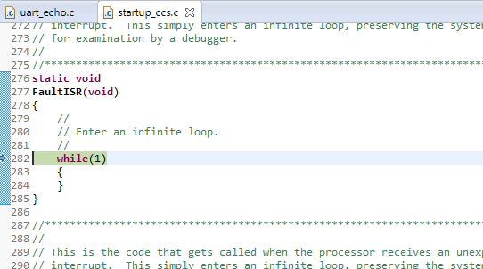
1) data trasmit and receive some time working properly through UART 4. after that, control goes to Fault interrupt loop.

2) and also some times controller reset, after that interrupt is not working.

I donot know why this is happened.Kindly suggest me ragarding this. 


Regards,

Sathish.

  • And famed, gleaming, "Game Show Car" is behind which (UART) Door?

    We have as much chance of answering that as your UART via RS485 difficulty.

    (Some) detail is required...

  • Hello Sathish,

    No code, no reference, and you want us to suggest what the issue solution could be. May be a read of the following post would help in first identifying the source of issue #1:

    e2e.ti.com/.../374640

    Regards
    Amit
  • I recommend working with the max485 for conversion to serial TTL to RS-485 , it works same the max232 to communicate for a pc host with the serial interface for example .
  • Hello Andres,

    I am not sure if the issue is resolved or not? Can you please elaborate?

    Regards
    Amit
  • Hi Amit,

    Thanks for your reply,

    I am configure uart 0, uart 3, uart 4 and GPIO as below. uart 0 and uart 3 is used for RS232 communication and Uart 4 for RS485 communication. And I used RS485 enable pin GPIO D-pin0, and application is that every 5 sec I send request using RS485 to the device. response data is received from the interrupt. that code is attached here.

    problem is that,

    1) after 3 or 4 time only, data read properly after that it will go to fault interrupt loop.

    2) some time error --- No source available for "SysCtlDelay()

    3) some time error --  No source available at 0x0.

    configuration:

    Init()

    {

        ROM_FPUEnable();
        ROM_FPULazyStackingEnable();

        //
        // Set the clocking to run directly from the crystal.
        //
        ROM_SysCtlClockSet(SYSCTL_SYSDIV_1 | SYSCTL_USE_OSC | SYSCTL_OSC_MAIN |
                           SYSCTL_XTAL_16MHZ);

        ROM_SysCtlPeripheralEnable(SYSCTL_PERIPH_GPIOD);

        ROM_GPIOPinTypeGPIOOutput(GPIO_PORTD_BASE, GPIO_PIN_0 | GPIO_PIN_1 | GPIO_PIN_2 | GPIO_PIN_3);


        //
        // Enable the peripherals used by this example.
        //
        ROM_SysCtlPeripheralEnable(SYSCTL_PERIPH_UART0);
        ROM_SysCtlPeripheralEnable(SYSCTL_PERIPH_GPIOA);

        //
        // Enable the peripherals used by this example.
        //
        ROM_SysCtlPeripheralEnable(SYSCTL_PERIPH_UART3);
        ROM_SysCtlPeripheralEnable(SYSCTL_PERIPH_GPIOC);
        ROM_SysCtlPeripheralEnable(SYSCTL_PERIPH_UART4);

        //
        // Enable processor interrupts.
        //
        ROM_IntMasterEnable();

        //
        // Set GPIO A0 and A1 as UART pins.
        //
        GPIOPinConfigure(GPIO_PC6_U3RX);
        GPIOPinConfigure(GPIO_PC7_U3TX);
        ROM_GPIOPinTypeUART(GPIO_PORTC_BASE, GPIO_PIN_6 | GPIO_PIN_7);

        //
        // Set GPIO A0 and A1 as UART pins.
        //
        GPIOPinConfigure(GPIO_PA0_U0RX);
        GPIOPinConfigure(GPIO_PA1_U0TX);
        ROM_GPIOPinTypeUART(GPIO_PORTA_BASE, GPIO_PIN_0 | GPIO_PIN_1);

           GPIOPinConfigure(GPIO_PC4_U4RX);
        GPIOPinConfigure(GPIO_PC5_U4TX);
           ROM_GPIOPinTypeUART(GPIO_PORTC_BASE, GPIO_PIN_4 | GPIO_PIN_5);

        //
        // Configure the UART for 115,200, 8-N-1 operation.
        //
        ROM_UARTConfigSetExpClk(UART0_BASE, ROM_SysCtlClockGet(), 9600,
                                (UART_CONFIG_WLEN_8 | UART_CONFIG_STOP_ONE |
                                 UART_CONFIG_PAR_NONE));

        //
         // Configure the UART for 115,200, 8-N-1 operation.
         //
         ROM_UARTConfigSetExpClk(UART3_BASE, ROM_SysCtlClockGet(), 9600,
                                 (UART_CONFIG_WLEN_8 | UART_CONFIG_STOP_ONE |
                                  UART_CONFIG_PAR_NONE));


            ROM_UARTConfigSetExpClk(UART4_BASE, ROM_SysCtlClockGet(), 9600,
                                            (UART_CONFIG_WLEN_8 | UART_CONFIG_STOP_ONE |
                                             UART_CONFIG_PAR_NONE));


        //
        // Enable the UART interrupt.
        //
        ROM_IntEnable(INT_UART0);
        ROM_UARTIntEnable(UART0_BASE, UART_INT_RX | UART_INT_RT);

        //
        // Enable the UART interrupt.
        //
        ROM_IntEnable(INT_UART3);
        ROM_UARTIntEnable(UART3_BASE, UART_INT_RX | UART_INT_RT);

        ROM_IntEnable(INT_UART4);
        ROM_UARTIntEnable(UART4_BASE, UART_INT_RX | UART_INT_RT);

    }

    /*****************************************************************************************************************************/

    Application:

        while(1)
        {
            for(j=0;j<5000;j++)
            {
                SysCtlDelay(SysCtlClockGet() / (1000 * 3));
            }

           Read_Meter_Data();
    }


    /**************************************************************************************************************************/


    void Read_Meter_Data(void)
    {
        unsigned int count=0, Length_Arr=0, j=0, enable=0, qq=0;

        RS485_Send(RS485ArrSNRM, 26); // 26 //(sizeof(RS485ArrSNRM)/sizeof(RS485ArrSNRM[0]))

        for(j=0;j<2000;j++){SysCtlDelay(SysCtlClockGet() / (1000 * 3));}
    }


    /***********************************************************************************************************************/

    //*****************************************************************************
    //
    // The UART interrupt handler.
    //
    //*****************************************************************************
    void
    UART485IntHandler(void)
    {
        uint32_t ui32Status4;

        //
        // Get the interrrupt status.
        //
        ui32Status4 = ROM_UARTIntStatus(UART4_BASE, true);

        //
        // Clear the asserted interrupts.
        //
        ROM_UARTIntClear(UART4_BASE, ui32Status4);

        //
        // Loop while there are characters in the receive FIFO.
        //
        while(ROM_UARTCharsAvail(UART4_BASE))
        {

            RS485_Rx_Buf[RS485_BufLen++] = ROM_UARTCharGetNonBlocking(UART4_BASE);

        }
    }
    /*****************************************************************************************************************************/


    void RS485_Send(uint8_t *pui8Buffer4, unsigned int  ui32Count4)
    {
        unsigned int delay_1=0, delay12=0;


        RS485_BufLen=0;

        GPIOPinWrite(GPIO_PORTD_BASE, (GPIO_PIN_0), (GPIO_PIN_0 ));  // transmit enable

        for(delay_1=0;delay_1<3;delay_1++)
        {
            SysCtlDelay(SysCtlClockGet() / (1000 * 3));
        }

        //
        // Loop while there are more characters to send.
        //
        while(ui32Count4--)
        {

            //
            // Write the next character to the UART.
            //
            ROM_UARTCharPutNonBlocking(UART4_BASE, *pui8Buffer4);

            for(delay_1=0;delay_1<5;delay_1++)
            {
                SysCtlDelay(SysCtlClockGet() / (1000 * 3));
            }

        }

        GPIOPinWrite(GPIO_PORTD_BASE, GPIO_PIN_0, 0);  // receive enable
       
    }


    Regards,

    Sathish.

  • Hello Sathish,

    There is nothing obvious wrong with the code. When the debugger mentions no source code for SysCtlDelay it is because you are using the driverlib version of SysCtlDelay for which the source code is not there in the precompiled version. You can get rid of that by recompiling the driverlib and using the new local copy,

    When it goes to the fault handler, did you check what the FAULTSTAT shows up? Did you change the Stack Size?

    Regards
    Amit
  • Hi Amit,

    I already included SysCtl.c and SysCtl.h into my project. and I set my stack size is 1024 and heap size is 320. but same problem is coming as I mentioned above.
    And 1) One thing, I noted that when I continuously sending data to the uart , that time control goes to the fault interrupt.
    2) some time SysCtlDelay() is not working properly.
    3) some times, controller reset is happened.

    kindly suggest me regarding these problem

    Regards,
    Sathish.
  • Hello Sathish

    Did you check the FAULTSTAT register value and looked at the same?

    There are too many issues you are trying to follow lead on, first one first, the fault diagnosis is important

    Regards
    Amit
  • Amit Ashara said:
    There are too many issues you are trying to follow lead on, first one first

    So true - and perhaps more easily said (and far better remembered) as, "KISS!"   (it appears "near universal" that new posters try to do too much - too often...)   Might KISS be on a "banned" list?

    We note that the always suspect PD0 "rides again" this post - might it have claimed (yet another) victim?   (cb1 "NMI plague counter" overfowed after 10^6...)

    [edit] 16:43...Whoops - wrong "plague!"    PD0 is one of the 2 pins "attached" to another MCU pin via 0Ω plague-istor.

  • Hi,

    @ Amit, I donot know that what i need to check in that STATUS register, kindly suggest me about that.

    @cb1_mobile, sorry, I didn't understand your word, But I think that I want to put one 0 ohm resistor in PD0 pin right, I will check and tell you about that.


    Thanks you very much for your support,

    regards,

    Sathish.


  • Hi,

    It is quite normal what happens here with your code. Look at this line in your interrupt routine:

    RS485_Rx_Buf[RS485_BufLen++] = ROM_UARTCharGetNonBlocking(UART4_BASE);


    The question: what is the length of your receiving buffer? it overflows after a number of chars, resulting in fault interrupt.

    You should use defensive programming - test first the length of receiving buffer and if at the limit either do not do anything , resulting in lost chars, either use a circular buffer - you have such bundle of routines in /utils/ringbuf.c file. (or use UARTStdio).

    Petrei 

  • hi,

    @ Petrei , RS485_Rx_Buf[RS485_BufLen++] -- here, I declared unsigned char RS485_Rx_Buf[512] and RS485_BufLen declared as unsigned int.
    And when I send a request to the the device, I put RS485_BufLen as 0, and I received the max byte is 50. so I thought that there is no problem in the RS485_Rx_Buf and RS485_BufLen that means buffer overflow or Buffer length out of range.

    kindly suggest me regarding this, If may be I wrong.

    Thanks for your valuable response.

    Regards,
    Sathish.
  • Hi,

    OK, your precautions about buffer length are good, although you may shorten that if only 50 bytes ever received.

    Some more things to check:

    a) as cb1 told you, you must remove the 0 ohm resistor found on PD0, since this means collision with ICDI chip;

    b) nothing is specified about the length of UART's FIFO - you may modify it if needed. Keep in mind that many UARTs working with the same baud rate could be problematic if interrupts are simultaneous - this may happen since you have long delays in both receiving and sending routines. Try to remove them, or keep a very short delay - a said 2 cycle delay on pin level change is shorter than function return from stack, so including such delay when using library functions is not needed (I do not use such...), but needed when direct register addressing, which is not your case.

    c) TI has an application note about managing hardware faults - grab that, read it, understand it an use it every time when you have such problems.

    d) try to analyze more the behavior of your code - when it blocks - how many characters are  sent or received -

    Petrei 

  • Re: PD0,

    First - thanks to friend Petrei for his input.

    In further detail - both PD0 & PD1 "direct connect" to other MCU pins via 0Ω resistors.   (this is marked {in mice type} on the 123 L-Pad's schematic - most miss this "subdued" warning)

    It proves wise to remove these resistors so that PD0 & PD1 are not potentially disturbed or damaged even by this (often unwanted) MCU to MCU connection.

  • Hello Sathish

    I mentioned the FAULTSTAT register. Please open the data sheet and search for the same, and you will see what it's address is. Petrei has mentioned something better, an application note on www.ti.com (I expect you to search the same)

    Consider a scenario that the RS485_BufLen does not get to 0. Instead put a SW guard band stating that if the value is >49 then it will remain at 49.

    Regards
    Amit