This thread has been locked.

If you have a related question, please click the "Ask a related question" button in the top right corner. The newly created question will be automatically linked to this question.

TIVA TM4C123H6P GPIO+DMA

Other Parts Discussed in Thread: TM4C1233H6PM

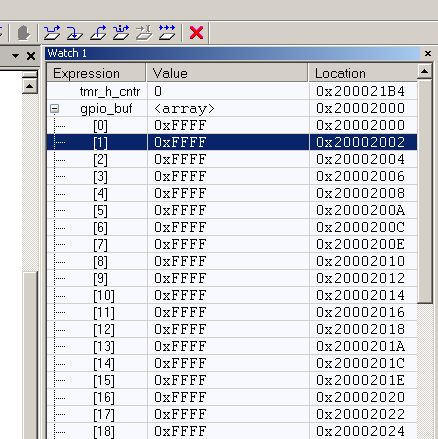
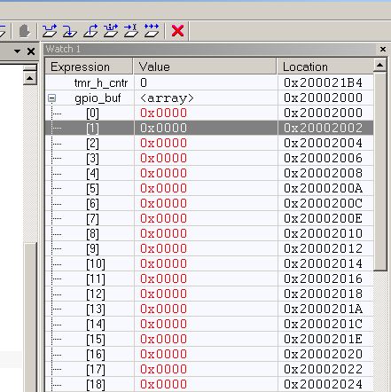
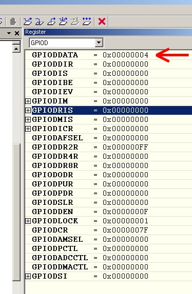
I want to use DMA for reading information from GPIO (for example, from GPIOD) pins. I tried to do that but I've got a fault: I always read 0 instead of the real state, but if I read it manually I get a good result.

Trigger for the DMA transaction is Timer 0 or manual trigger.

Is it generally possible?

  • Hello Tankist,

    It is possible to have a trigger from one peripheral to read another peripheral. Have you enabled the clock to the GPIO. No code????

    Regards
    Amit
  • There is the source code for the part of my application. The controller works on 80 MHz.

    // DMA channel
    #define DMA_CHANNEL		UDMA_CHANNEL_TMR0A
    // buffer size
    #define DMA_BUF_SIZE	100
    
    // quantisation frequency
    unsigned long ulFrequency = 8000;
    
    // input buffer to store values from port D
    uint16_t gpio_buf[DMA_BUF_SIZE];
    
    // this is necessary
    #pragma data_alignment=1024
    unsigned char ucControlTable[1024];
    
    // -------------------------- subroutines ----------------------------------
    
    void timer_init()
    {
    	unsigned long ulPeriod;
    
        // switch TIMER clock on
    	SysCtlPeripheralEnable(SYSCTL_PERIPH_TIMER0);
    	// full width timer
    	TimerConfigure(TIMER0_BASE, TIMER_CFG_32_BIT_PER);
    	// calculate the period
    	ulPeriod = (80000000UL / ulFrequency);
    	TimerLoadSet(TIMER0_BASE, TIMER_A, ulPeriod - 1);
    }
    
    void timer_enable()
    {
    	// enable my timer
    	TimerEnable(TIMER0_BASE, TIMER_A);
    }
    
    void dma_init(void)
    {
    	// fill the buffer with a constant: I can watch transactions in the WatchWindow
    	memset(gpio_buf, 0xFF, sizeof(gpio_buf));
    	
    	// enable of the monitoring port
    	SysCtlPeripheralEnable(SYSCTL_PERIPH_GPIOD);
        GPIOPinTypeGPIOInput(GPIO_PORTD_BASE, GPIO_PIN_0 | GPIO_PIN_1 | GPIO_PIN_2 | GPIO_PIN_3);
    
        // switch DMA clock on
        SysCtlPeripheralEnable(SYSCTL_PERIPH_UDMA);
        uDMAEnable();
        uDMAControlBaseSet(ucControlTable);
    	
        // fill attributes
        uDMAChannelAttributeDisable(DMA_CHANNEL,
        		UDMA_ATTR_ALTSELECT
        		| UDMA_ATTR_USEBURST
        		| UDMA_ATTR_REQMASK
        		| UDMA_ATTR_HIGH_PRIORITY);
    
        // primary transaction set
        uDMAChannelControlSet(DMA_CHANNEL | UDMA_PRI_SELECT,
        		UDMA_SIZE_16 |				// word size
        		UDMA_SRC_INC_NONE |			// from register (GPIO_PORTD_BASE + GPIO_O_DATA) so constant
        		UDMA_DST_INC_16 |			// destination in memory so increment
        		UDMA_ARB_1);				// one word per transaction
       	// primary transfer set
        uDMAChannelTransferSet(DMA_CHANNEL | UDMA_PRI_SELECT,
        		UDMA_MODE_BASIC,			// linear filling
                (void *)(GPIO_PORTD_BASE + GPIO_O_DATA),	// GPIOD data register
                gpio_buf,					// my buffer
                DMA_BUF_SIZE);				// buffer size
      
    	// enable DMA - waiting for the trigger event
        uDMAChannelEnable(DMA_CHANNEL);
    }
    
    // ------------------------- main application function -----------------------------
    void board_init()
    {
    	timer_init();	// setup a timer - it doesn't work now
    	dma_init();		// setup DMA - it suspend for some events
    	timer_enable();	// start my timer - since that all transactions happen
    
    	IntMasterEnable();
    }

  • Hello Tankist

    I ran the program with one change (I could not find where you got TIMER_CFG_32_BIT_PER  from)

    TimerConfigure(TIMER0_BASE, TIMER_CFG_32_BIT_PER);

    to

    TimerConfigure(TIMER0_BASE, TIMER_CFG_PERIODIC);

    And the DMA transfer completes without bus faults.

    Attached is a simplified code that I ran on my setup.

    #include <stdbool.h>
    #include <stdint.h>
    #include "inc/hw_gpio.h"
    #include "inc/hw_ints.h"
    #include "inc/hw_memmap.h"
    #include "inc/hw_types.h"
    #include "driverlib/gpio.h"
    #include "driverlib/interrupt.h"
    #include "driverlib/pin_map.h"
    #include "driverlib/sysctl.h"
    #include "driverlib/timer.h"
    #include "driverlib/udma.h"
    #include "utils/uartstdio.h"
    
    // DMA channel
    #define DMA_CHANNEL		UDMA_CHANNEL_TMR0A
    // buffer size
    #define DMA_BUF_SIZE	100
    
    // quantisation frequency
    unsigned long ulFrequency = 8000;
    
    // input buffer to store values from port D
    uint16_t gpio_buf[DMA_BUF_SIZE];
    
    // this is necessary
    #pragma DATA_ALIGN(ucControlTable, 1024)
    unsigned char ucControlTable[1024];
    
    void timer_init()
    {
    	unsigned long ulPeriod;
    
        // switch TIMER clock on
    	SysCtlPeripheralEnable(SYSCTL_PERIPH_TIMER0);
    	// full width timer
    	TimerConfigure(TIMER0_BASE, TIMER_CFG_PERIODIC); //TIMER_CFG_32_BIT_PER
    	// calculate the period
    	ulPeriod = (80000000UL / ulFrequency);
    	TimerLoadSet(TIMER0_BASE, TIMER_A, ulPeriod - 1);
    }
    
    void timer_enable()
    {
    	// enable my timer
    	TimerEnable(TIMER0_BASE, TIMER_A);
    }
    
    void dma_init(void)
    {
    	// enable of the monitoring port
    	SysCtlPeripheralEnable(SYSCTL_PERIPH_GPIOD);
        GPIOPinTypeGPIOInput(GPIO_PORTD_BASE, GPIO_PIN_0 | GPIO_PIN_1 | GPIO_PIN_2 | GPIO_PIN_3);
    
        // switch DMA clock on
        SysCtlPeripheralEnable(SYSCTL_PERIPH_UDMA);
        uDMAEnable();
        uDMAControlBaseSet(ucControlTable);
    
        // fill attributes
        uDMAChannelAttributeDisable(DMA_CHANNEL,
        		UDMA_ATTR_ALTSELECT
        		| UDMA_ATTR_USEBURST
        		| UDMA_ATTR_REQMASK
        		| UDMA_ATTR_HIGH_PRIORITY);
    
        // primary transaction set
        uDMAChannelControlSet(DMA_CHANNEL | UDMA_PRI_SELECT,
        		UDMA_SIZE_16 |				// word size
        		UDMA_SRC_INC_NONE |			// from register (GPIO_PORTD_BASE + GPIO_O_DATA) so constant
        		UDMA_DST_INC_16 |			// destination in memory so increment
        		UDMA_ARB_1);				// one word per transaction
       	// primary transfer set
        uDMAChannelTransferSet(DMA_CHANNEL | UDMA_PRI_SELECT,
        		UDMA_MODE_BASIC,			// linear filling
                (void *)(GPIO_PORTD_BASE + GPIO_O_DATA),	// GPIOD data register
                gpio_buf,					// my buffer
                DMA_BUF_SIZE);				// buffer size
    
    	// enable DMA - waiting for the trigger event
        uDMAChannelEnable(DMA_CHANNEL);
    }
    
    
    int
    main(void)
    {
        //
        // Set the clocking to run directly from the external crystal/oscillator.
        // TODO: The SYSCTL_XTAL_ value must be changed to match the value of the
        // crystal on your board.
        //
        SysCtlClockSet(SYSCTL_SYSDIV_2_5 | SYSCTL_USE_PLL | SYSCTL_OSC_MAIN |
                       SYSCTL_XTAL_16MHZ);
    
    	timer_init();	// setup a timer - it doesn't work now
    	dma_init();		// setup DMA - it suspend for some events
    	timer_enable();	// start my timer - since that all transactions happen
    
    	IntMasterEnable();
    
    	//
        // Loop forever while the PWM signals are generated.
        //
        while(1)
        {
        }
    }
    

    Regards

    Amit

  • I'm sorry for the involuntary fraud, it was mistake in the name of the processor. My device's name is LX4F120H5QRF. It's old part so I meant TM4C1233H6PM as the analog, but I've done a mistake in the name. I use Stellaris Library for the chip supporting which may consist different definitions like TIMER_CFG_32_BIT_PER. This device is exactly Cortex-M4 processor so I put my question in this thread.

    Maybe I badly described my problem. As I see DMA works (values in gpio_buf change its state during working), but works incorrectly. The problem is values that DMA stores in gpio_buf doesn't match real signals on controller's pins. It seems like DMA reads from the wrong register. There are some screenshots from my IDE:

    1) State of gpio_buf before timer_enable();

    2) State of gpio_buf after timer_enable();

    As you can see it fills so I'm sure that DMA works.

    3) State of the GPIOD data register (source of DMA transactions):

    As you can see the one pin has the high level so it's impossible to get a value equal to 0 after the DMA transaction.

    I expect that I'll get a value 0x0004 in my buffer, but it isn't so. Amit, could you check does it work properly on your platform?

  • Hello Tankist,

    The GPIO module uses bit banded scheme to read pins (details in the data sheet). The define GPIO_O_DATA is 0x0 and this will cause it to read 0x0 always even though the GPIODDATA shows 0x4. Instead of using GPIO_O_DATA in the UDMA source buffer use the offset 0x3FC

    uDMAChannelTransferSet(DMA_CHANNEL | UDMA_PRI_SELECT,
    UDMA_MODE_BASIC, // linear filling
    (void *)(GPIO_PORTD_BASE + 0x3FC), // GPIOD data register
    gpio_buf, // my buffer
    DMA_BUF_SIZE); // buffer size

    I will file a bug for this correction of GPIO_O_DATA to be 0x3FC.

    Regards
    Amit
  • Amit, thank you very much! Now it works well.
  • Hi Amit,

    (Another) great "get" - we missed this as well - thank you.

    (we note that our "fraud" was far from vouluntary...[cell door slams shut])

  • Hello cb1, All

    There was a bit of complication in modifying the underlying API call for GPIOPinRead and GPIOPinWrite, but it seems that we can work it out by using a SUB instruction (when compiled and linked). However it would need to approved for fix.

    Regards
    Amit