The TQFP-128 package diagram in datasheet is not the same thing as (S-PQFP-G128) footprint layout of PCB pads.
http://www.ti.com/lit/ml/mpqf013/mpqf013.pdf
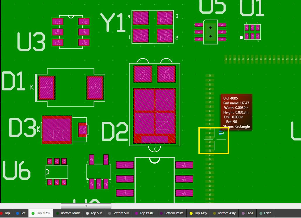
The layout of PCB pads mathematically measures 12.420mm given 0.4mm spacing, is that (center) of pin dimension line 12.4mm hard to tell? Measured from what might be the center of the 2 pins is hard to know for sure even at extreme magnification.
Pin width 0.23mm to 0.13mm +0.05 (M) is the tolerance? Some vendor appear to infer both as max/min other vendors seem to add the min to the max when no (M) tolerance is given. These 2 dimensions seem to have a very wide variance, + 0.05m (M) added we get 0.28mm to 0.18mm almost double the pin width. My footprint pads are now 0.226mm wide, any wider causes DRC rules violations in the space between pads, again we get 12.42mm with .226mm wide pin @0.4mm centers x 32 pins/side. BYW (,) UIA is a Euro standard separator, (.) is same thing SAE standard.
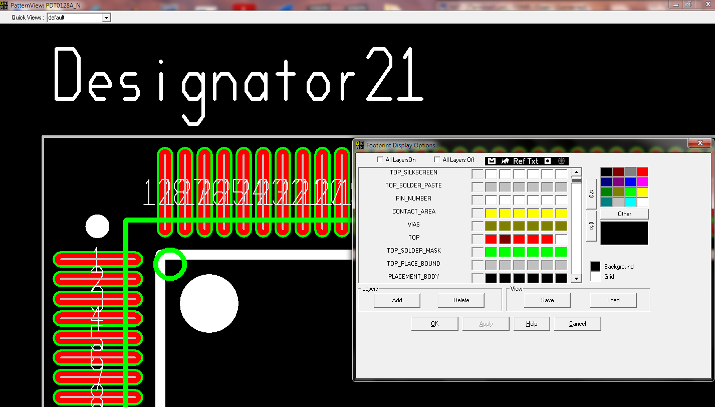
1. Where to find the TI recommended G128 solder mask area details and or solder paste stencil diagrams?
2. TI takes measures for smaller packages to relate solder mask details. TQFP package is seeming highly prone to solder shorts given the density of pins. Is that an incorrect assumption?