Hi guys - more UART questions for you! Right now, I'm trying to get communications up and running with an IMU board. I set up UART2 to communicate with is Adafruit's BNO055. I'm getting into my TX interrupt, just fine, and according to my print statements I'm correctly shifting out byte by byte. However, I'm not getting into my RX interrupt (not getting anything back from the bno055).
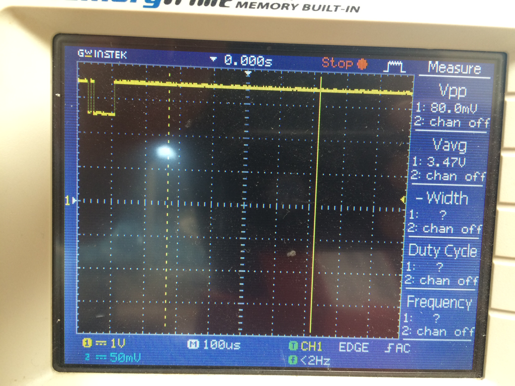
The first thing I chose to check was that my data was going out. I put a logic analyzer on D7, which is UART2 TX. Even though I get into my TX interrupt, so I know I'm calling the UARTCharPut(UART2_BASE, array_tx[index]) line, I'm not seeing anything on the logic analyzer. The line seems to just stay high. I tried checking out different modes on the logic analyzer, then setting it to trigger on a rising or falling edge. It doesn't see either. So even though I'm getting into the TX interrupt, no data appears to be going out on D7. Does anyone have any ideas for what might be going on? Is there something about UART2 or D7 I might be missing? I've attached my UART2 init code and ISR. Thank you for any insights!
#include <stdint.h>
#include <stdbool.h>
#include "hw_gpio.h"
#include "hw_ints.h"
#include "hw_nvic.h"
#include "hw_sysctl.h"
#include "hw_uart.h"
#include "hw_types.h"
#include "hw_memmap.h"
#include "gpio.h"
#include "pwm.h"
#include "sysctl.h"
#include "cycle.h"
#include "uart.h"
#include "pin_map.h"
#include "interrupt.h"
#include "termio.h"
#include "rom.h"

#define printf    UARTprintf
#define TicksPerMS 40000
#define ALL_BITS (0xff<<2)
#define index_start_byte 0
#define index_rw 1
#define index_reg_address 2
#define index_data_length 3
#define index_data 4
#define write 0x00
#define read 0x01
#define reg_address_page 0x07
#define reg_address_opr 0x3D
#define reg_address_lia 0x28
#define ndof_mode 0x0C
#define page_zero 0x00
#define start_byte 0xAA
#define packet_length_write 4
#define packet_length_read 3

/*---------------------------- Module Variables ---------------------------*/
static uint8_t array_tx[20]; //array to hold the byte sequence we send
static uint8_t array_rx[20];
static uint8_t tx_data = 0x00; //the byte that actually matters
static uint8_t rx_data = 0x00; //the byte that actually matters
static uint8_t index=1;
static uint8_t index_rx=0;
static bool pageselectdone = false;
static bool oprmodeselectdone = false;

/*---------------------------- Module Functions ---------------------------*/
void uart_init(void);
void ConfigureUART(void);
bool isdone_pageselect(void);
bool isdone_oprmode(void);
void isr_uart1(void);
void isr_uart2(void);

void uart2_init(){
	//initializes UART2
	//sets up transmit and receive interrupts
	//0. Init Clock to UART2 and Port D
	SysCtlPeripheralEnable(SYSCTL_PERIPH_UART2);
	SysCtlPeripheralEnable(SYSCTL_PERIPH_GPIOD);
	//Give it time for clocks to start
	SysCtlDelay(10);
	//Disable UART before programming
	UARTDisable(UART2_BASE);
	//1.  set baud rate, txe/rxe, stp2 (clear then and fen), and wlen (8 bit_)
	UARTConfigSetExpClk(UART2_BASE, SysCtlClockGet(), 115200, (UART_CONFIG_WLEN_8 | UART_CONFIG_STOP_ONE | UART_CONFIG_PAR_NONE));
	UARTFIFODisable(UART2_BASE); //DISABLE FIFO. This should make my interrupt every time I get a byte.
	//1.5. Set up AFSEL To D6, D7
	GPIOPinConfigure(GPIO_PD6_U2RX);
	GPIOPinConfigure(GPIO_PD7_U2TX);
	//Set D6 as Input (RX) and D7 as Output (TX)
	GPIOPinTypeGPIOOutput(GPIO_PORTD_BASE, GPIO_PIN_7);
	GPIOPinTypeGPIOInput(GPIO_PORTD_BASE, GPIO_PIN_6);
	//A little redundancy shouldn't hurt.
	GPIOPinTypeUART(GPIO_PORTD_BASE, GPIO_PIN_6 | GPIO_PIN_7);
	//Enable Global NVIC Interrupt
	IntEnable(INT_UART2);
	//Enable Local Interrupts
	UARTIntEnable(UART2_BASE, (UART_INT_TX | UART_INT_RX)); //enable Tx and Rx int
	UARTTxIntModeSet(UART2_BASE, UART_TXINT_MODE_EOT); //set Tx mode to EOT
	UARTFIFOLevelSet(UART2_BASE, UART_FIFO_TX1_8, UART_FIFO_RX1_8); //set Rx to trigger with two bytes
	//Disable for now so I don't get stuck in the TX isr.
	UARTIntDisable(UART2_BASE, UART_INT_TX);
	//Link a function to the UART Interrupt
	UARTIntRegister(UART2_BASE, isr_uart2);
	//Enable UART2
	UARTEnable(UART2_BASE);

	//these will change based on our state, but we can use this as a table of contents
	array_tx[index_start_byte] = start_byte;
	array_tx[index_rw] = write;
	array_tx[index_reg_address] = reg_address_page;
	array_tx[index_data_length] = 0x01;
	array_tx[index_data] = page_zero;
}

void isr_uart2(void){
	uint32_t trigger;
	trigger = UARTIntStatus(UART2_BASE, true);
	if ((trigger & UART_INT_RX)== UART_INT_RX){
		//ISR triggers each time I receive a byte.
		printf("RX: UART2 ISR\n");
		UARTIntClear(UART2_BASE, UART_INT_RX);
		array_rx[index_rx] = UARTCharGet(UART2_BASE);


		if (array_rx[0] == 0xEE && index_rx != 0){
			index_rx = 0;
			printf("RX: OxEE // Write Response \n");
			switch (array_rx[1]){
				case 0x01: printf("WRITE_SUCCESS \n");
					break;
				case 0x03: printf("WRITE_FAIL \n");
					break;
				case 0x04: printf("REGMAP_INVALID_ADDRESS \n");
					break;
				case 0x06: printf("WRONG_START_BYTE \n");
					break;
				case 0x07: printf("BUS_OVER_RUN_ERROR \n");
					break;
				case 0x08: printf("MAX_LENGTH_ERROR \n");
					break;
				case 0x09: printf("MIN_LENGTH_ERROR \n");
					break;
				case 0x0A: printf("RECEIVE_CHARACTER_TIMEOUT \n");
					break;
			}
		}

		if (array_rx[0] == 0xBB && index_rx>packet_length_read){
			printf("RX: 0xBB // Data Packet Received \n");
			index_rx=0;
		}

		index_rx++;

	}
	if ((trigger & UART_INT_TX) == UART_INT_TX){
		//printf("TX: In  UART2 Transmit ISR\n");
		UARTIntClear(UART2_BASE, UART_INT_TX);
		UARTCharPut(UART2_BASE, array_tx[index]);
		//printf("%u \n", index);
		index++;

		if (pageselectdone == false && (index>packet_length_write)){
			//printf("TX: Page Select Done. Setting Boolean True. \n");
			UARTIntDisable(UART2_BASE, UART_INT_TX);
			index=1;
			array_tx[index_reg_address] = reg_address_opr;
			array_tx[index_data] = ndof_mode;
			pageselectdone = true;
		}

		else if (pageselectdone == true && oprmodeselectdone == false && index>packet_length_write){
			//printf("here1 \n");
			UARTIntDisable(UART2_BASE, UART_INT_TX);
			index=1;
			array_tx[index_reg_address] = reg_address_lia;
			array_tx[index_rw] = read;
			array_tx[index_data_length] = 0x06;
			oprmodeselectdone = true;
			//Start regular 200 ms timer. Within the timer interrupt I will query the LIA.
		}

		else if (pageselectdone==true && oprmodeselectdone==true && index>packet_length_read){
			//printf("here2 \n");
			UARTIntDisable(UART2_BASE, UART_INT_TX);
			index=1;
		}

	}
}