Other Parts Discussed in Thread: TM4C123GH6PZ
Hello,
We are using the TM4C123GH6PZ in an application that requires the following 12 PWM channels to output 0%-100% (the other 4 channels are also used, but do not require the same type of control):
- M0PWM0
- M0PWM1
- M0PWM2
- M0PWM3
- M1PWM0
- M1PWM1
- M1PWM2
- M1PWM3
- M1PWM4
- M1PWM5
- M1PWM6
- M1PWM7
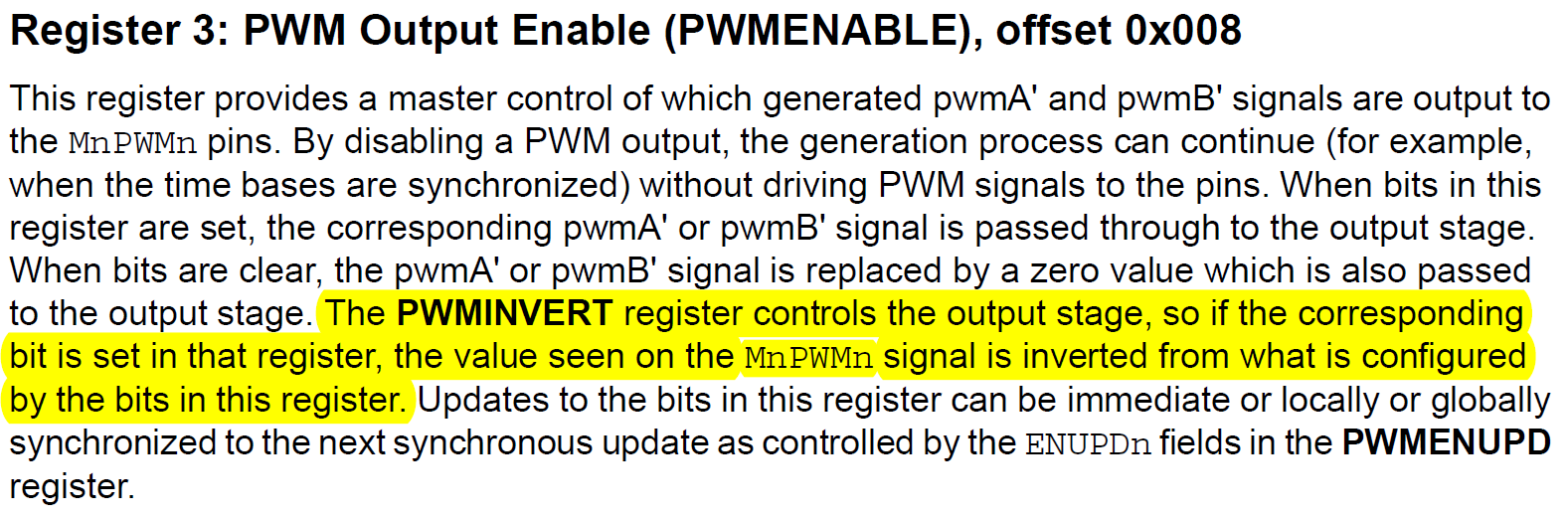
Each module is synced together, which has been working to date as we use it for triggering an ADC read. Each generator pair (i.e. M0PWM0/M0PWM1) is used such that if one channel is PWMing, the other is high (100%). We have been attempting to achieve the 100% with an inverted PWM channel with a width setting of 0, based on our interpretation of previous posters on the topic.
The problem is, it only sometimes works... other times we find that the 100% pin is actually a logic low (0%) at the output, despite no change in the observed register values for PWMxCMPA/PWMxCMPB/PWMINVERT. We have tried changing hardware, but the problem follows. Does anyone have any idea what is causing this issue, or what we are doing wrong? Can it be fixed, or do we need to toggle the pin between PWM and GPIO to achieve reliable 0%/100% operation?
I can attach more detailed code if required, but here is the specific section that seems to periodically fail (the last section, where we invert the 0%)
		PWMOutputState(PWM0_BASE, PWM_OUT_0_BIT | PWM_OUT_1_BIT | PWM_OUT_2_BIT | PWM_OUT_3_BIT, false);
		PWMOutputState(PWM1_BASE, PWM_OUT_0_BIT | PWM_OUT_1_BIT | PWM_OUT_2_BIT | PWM_OUT_3_BIT |
									PWM_OUT_4_BIT | PWM_OUT_5_BIT | PWM_OUT_6_BIT | PWM_OUT_7_BIT, false);

		PWMPulseWidthSet(PWM0_BASE, PWM_OUT_0, 0);
		PWMPulseWidthSet(PWM0_BASE, PWM_OUT_2, 0);
		PWMPulseWidthSet(PWM1_BASE, PWM_OUT_0, 0);
		PWMPulseWidthSet(PWM1_BASE, PWM_OUT_2, 0);
		PWMPulseWidthSet(PWM1_BASE, PWM_OUT_4, 0);
		PWMPulseWidthSet(PWM1_BASE, PWM_OUT_6, 0);

		PWMOutputInvert(PWM0_BASE, PWM_OUT_0, false);
		PWMOutputInvert(PWM0_BASE, PWM_OUT_2, false);
		PWMOutputInvert(PWM1_BASE, PWM_OUT_0, false);
		PWMOutputInvert(PWM1_BASE, PWM_OUT_2, false);
		PWMOutputInvert(PWM1_BASE, PWM_OUT_4, false);
		PWMOutputInvert(PWM1_BASE, PWM_OUT_6, false);

		PWMPulseWidthSet(PWM0_BASE, PWM_OUT_1, 0);
		PWMPulseWidthSet(PWM0_BASE, PWM_OUT_3, 0);
		PWMPulseWidthSet(PWM1_BASE, PWM_OUT_1, 0);
		PWMPulseWidthSet(PWM1_BASE, PWM_OUT_3, 0);
		PWMPulseWidthSet(PWM1_BASE, PWM_OUT_5, 0);
		PWMPulseWidthSet(PWM1_BASE, PWM_OUT_7, 0);

		PWMOutputInvert(PWM0_BASE, PWM_OUT_1, false);
		PWMOutputInvert(PWM0_BASE, PWM_OUT_3, false);
		PWMOutputInvert(PWM1_BASE, PWM_OUT_1, false);
		PWMOutputInvert(PWM1_BASE, PWM_OUT_3, false);
		PWMOutputInvert(PWM1_BASE, PWM_OUT_5, false);
		PWMOutputInvert(PWM1_BASE, PWM_OUT_7, false);

		PWMOutputState(PWM0_BASE, PWM_OUT_0_BIT | PWM_OUT_1_BIT | PWM_OUT_2_BIT | PWM_OUT_3_BIT, true);
		PWMOutputState(PWM1_BASE, PWM_OUT_0_BIT | PWM_OUT_1_BIT | PWM_OUT_2_BIT | PWM_OUT_3_BIT |
									PWM_OUT_4_BIT | PWM_OUT_5_BIT | PWM_OUT_6_BIT | PWM_OUT_7_BIT, true);

		delayMS(1);

		PWMOutputState(PWM0_BASE, PWM_OUT_0_BIT | PWM_OUT_1_BIT | PWM_OUT_2_BIT | PWM_OUT_3_BIT, false);
		PWMOutputState(PWM1_BASE, PWM_OUT_0_BIT | PWM_OUT_1_BIT | PWM_OUT_2_BIT | PWM_OUT_3_BIT |
									PWM_OUT_4_BIT | PWM_OUT_5_BIT | PWM_OUT_6_BIT | PWM_OUT_7_BIT, false);

		PWMOutputInvert(PWM0_BASE, PWM_OUT_1, true);
		PWMOutputInvert(PWM0_BASE, PWM_OUT_3, true);
		PWMOutputInvert(PWM1_BASE, PWM_OUT_1, true);
		PWMOutputInvert(PWM1_BASE, PWM_OUT_3, true);
		PWMOutputInvert(PWM1_BASE, PWM_OUT_5, true);
		PWMOutputInvert(PWM1_BASE, PWM_OUT_7, true);

		PWMOutputInvert(PWM0_BASE, PWM_OUT_0, true);
		PWMOutputInvert(PWM0_BASE, PWM_OUT_2, true);
		PWMOutputInvert(PWM1_BASE, PWM_OUT_0, true);
		PWMOutputInvert(PWM1_BASE, PWM_OUT_2, true);
		PWMOutputInvert(PWM1_BASE, PWM_OUT_4, true);
		PWMOutputInvert(PWM1_BASE, PWM_OUT_6, true);

		PWMOutputState(PWM0_BASE, PWM_OUT_0_BIT | PWM_OUT_1_BIT | PWM_OUT_2_BIT | PWM_OUT_3_BIT, true);
		PWMOutputState(PWM1_BASE, PWM_OUT_0_BIT | PWM_OUT_1_BIT | PWM_OUT_2_BIT | PWM_OUT_3_BIT |
									PWM_OUT_4_BIT | PWM_OUT_5_BIT | PWM_OUT_6_BIT | PWM_OUT_7_BIT, true);
Following this bit of code, the intended PWM channel on each generator begins PWMing at a fixed duty cycle (this always works), while the other is supposed to stay high (this does not always work).
Note that we have tried alternate approaches as well, to no improvement or worse results, such as:
1) Setting the pulse width higher than the load, based on this piece from the datasheet:
Section 20.3.3 on PWM Comparators
"If either comparator match value is greater than the counter load value, then that comparator never outputs a High pulse."
2) Leaving the PWM signals always inverted (never attempting to drive true 0%, but rather something between X% and 100%)
Appreciate any help! Thanks in advance.