This thread has been locked.

If you have a related question, please click the "Ask a related question" button in the top right corner. The newly created question will be automatically linked to this question.

Trouble in chip select in communication SPI

Other Parts Discussed in Thread: TM4C123GH6PZ

Hello,

I'm implementing a SPI communication with the microcontroller TM4C123GH6PZ, but the chip select signalsI am driving through GPIO independently.

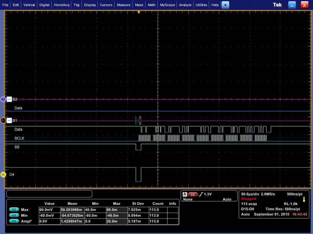
So far performed correctly I am sending as shown in the picture

However, to reprogram for sending other bytes, the chip select not operate in the same way and instructions appear to be performed sequentially. That is, it goes high before the bytes are sent as shown in fig.


Does anyone have any idea what happens?

This is the frame of the code 

...

GPIOPinWrite(GPIO_PORTF_BASE,GPIO_PIN_7 , 0x00);
SysCtlDelay(10);
SSIDataPut(SSI3_BASE, 'H');
SSIDataPut(SSI3_BASE, 'K');
SSIDataPut(SSI3_BASE, '_');
SSIDataPut(SSI3_BASE, 'P');
SSIDataPut(SSI3_BASE, 'i');
SSIDataPut(SSI3_BASE, 'x');
SSIDataPut(SSI3_BASE, 'q');
SSIDataPut(SSI3_BASE, 'u');
SSIDataPut(SSI3_BASE, 'i');

while(SSIBusy(SSI3_BASE))
{
}
SysCtlDelay(10);
GPIOPinWrite(GPIO_PORTF_BASE,GPIO_PIN_0 | GPIO_PIN_7, 0xFF);

  • Hello Sanchez,

    While the code seems to be functionally correct, there is something that does not seem right.

    1. GPIOPinWrite(GPIO_PORTF_BASE,GPIO_PIN_0 | GPIO_PIN_7, 0xFF); is being called but the GPIO_PIN_0 is a locked pin and w/o unlocking it cannot be used as a GPIO
    2. Where is GPIO_PIN_0 being made 0?
    3. Does the transaction fail, after one attempt, i.e. it works once and then it does not work again?

    Regards
    Amit
  • Thank Amit,

    Answering your questions:

    1.- Excuse me, the correct line is GPIOPinWrite(GPIO_PORTF_BASE, GPIO_PIN_7, 0xFF); where GPIO_PIN_7 is a chip select. I'm use GPIO because I have four slaves in the SPI communication and this the way that I implemented.
    2.- GPIO_PIN_0 is a chip select for other slave, but I activated with GPIOPinWrite(...) when I need communicate with other slave.
    3. The program worked well, sending information performed as shown in the first image. Make a change to the characters sent by the microcontroller and the problem is present and has not returned to work properly.

    Regards
    Juan Carlos
  • Hello Juan,

    Can you please send me the configuration of the SSI Master Block so that I can check it on a Test Board.

    Regards
    Amit
  • Hello Amit,

    This is the lines of configuration in my code:

    int main(void)
    {
    uint32_t pui32ADC0Value[10];
    uint32_t variable[10]={0x0103, 0x0102, 0x0101, 0x0100, 0x0D, 0x0C, 0x03, 0x02, 0x01, 0x00};
    float temp_mcu, termistor, MCU, Vo, RT;
    uint8_t i;
    //==================CONFIGURACIÓN DE RELOJ DE SISTEMA=================================================
    SysCtlClockSet(SYSCTL_SYSDIV_5| SYSCTL_USE_PLL | SYSCTL_OSC_MAIN | SYSCTL_XTAL_16MHZ);

    //==================HABILITACIÓN DE EEPROM===========================================================
    SysCtlPeripheralEnable(SYSCTL_PERIPH_EEPROM0);
    EEPROMInit();

    //==================HABILITACIÓN DE PUERTOS==============================================================
    SysCtlPeripheralEnable(SYSCTL_PERIPH_GPIOA);
    SysCtlPeripheralEnable(SYSCTL_PERIPH_GPIOB);
    SysCtlPeripheralEnable(SYSCTL_PERIPH_GPIOC);
    SysCtlPeripheralEnable(SYSCTL_PERIPH_GPIOD);
    SysCtlPeripheralEnable(SYSCTL_PERIPH_GPIOE);
    SysCtlPeripheralEnable(SYSCTL_PERIPH_GPIOF);
    SysCtlPeripheralEnable(SYSCTL_PERIPH_GPIOG);
    SysCtlPeripheralEnable(SYSCTL_PERIPH_GPIOH);
    SysCtlPeripheralEnable(SYSCTL_PERIPH_GPIOJ);
    SysCtlPeripheralEnable(SYSCTL_PERIPH_GPIOK);

    //==================CONFIRGUACION COMUNICACIONES SERIALES============================================
    //=====================UART's=======================================================================
    SysCtlPeripheralEnable(SYSCTL_PERIPH_UART0); //GPS
    GPIOPinConfigure(GPIO_PA0_U0RX); //GPS RX (26)
    GPIOPinConfigure(GPIO_PA1_U0TX); //GPS TX (27)
    GPIOPinTypeUART(GPIO_PORTA_BASE, GPIO_PIN_0 | GPIO_PIN_1);

    UARTConfigSetExpClk(UART0_BASE, SysCtlClockGet(), 115200,
    (UART_CONFIG_WLEN_8 | UART_CONFIG_STOP_ONE | UART_CONFIG_PAR_NONE));

    SysCtlPeripheralEnable(SYSCTL_PERIPH_UART1); //CPU
    GPIOPinConfigure(GPIO_PC5_U1TX); //CPU TX (24)
    GPIOPinConfigure(GPIO_PC4_U1RX); //CPU RX (25)
    GPIOPinTypeUART(GPIO_PORTC_BASE, GPIO_PIN_4 | GPIO_PIN_5);

    UARTConfigSetExpClk(UART1_BASE, SysCtlClockGet(), 115200,
    (UART_CONFIG_WLEN_8 | UART_CONFIG_STOP_ONE | UART_CONFIG_PAR_NONE));

    SysCtlPeripheralEnable(SYSCTL_PERIPH_UART3); //TS
    GPIOPinConfigure(GPIO_PC6_U3RX); //TS RX (25)
    GPIOPinConfigure(GPIO_PC7_U3TX); //TS TX (26)
    GPIOPinTypeUART(GPIO_PORTC_BASE, GPIO_PIN_6 | GPIO_PIN_7);

    UARTConfigSetExpClk(UART3_BASE, SysCtlClockGet(), 115200,
    (UART_CONFIG_WLEN_8 | UART_CONFIG_STOP_ONE | UART_CONFIG_PAR_NONE));

    //=====================SPI==========================================================================
    SysCtlPeripheralEnable(SYSCTL_PERIPH_SSI3);
    //GPIOPinConfigure(GPIO_PA3_SSI3FSS);

    GPIOPinConfigure(GPIO_PK0_SSI3CLK);
    GPIOPinConfigure(GPIO_PK3_SSI3TX);
    GPIOPinConfigure(GPIO_PK2_SSI3RX);
    GPIOPinTypeSSI(GPIO_PORTK_BASE,GPIO_PIN_0|GPIO_PIN_2|GPIO_PIN_3);
    SSIConfigSetExpClk(SSI3_BASE, SysCtlClockGet(), SSI_FRF_MOTO_MODE_0, SSI_MODE_MASTER, 400000, 8);
    SSIEnable(SSI3_BASE);

    //==CONFIGURACION DE TERMINALES CHIP SELECT==
    GPIOPinTypeGPIOOutput(GPIO_PORTG_BASE, GPIO_PIN_2 | GPIO_PIN_3); //PA6---->SPI CS4
    GPIOPinWrite(GPIO_PORTG_BASE, GPIO_PIN_2 | GPIO_PIN_3, 0xFF); //PA7---->SPI CS5

    GPIOPinTypeGPIOOutput(GPIO_PORTF_BASE, GPIO_PIN_7 | GPIO_PIN_0); //PA0---->SPI CS0 PA1---->SPI CS1
    GPIOPinWrite(GPIO_PORTK_BASE, GPIO_PIN_7 | GPIO_PIN_0, 0xFF); //PA2---->SPI CS2 PA3---->SPI CS3

    //=======================I2C==================================================================
    SysCtlPeripheralEnable(SYSCTL_PERIPH_I2C0);
    SysCtlPeripheralReset(SYSCTL_PERIPH_I2C0);

    GPIOPinConfigure(GPIO_PB2_I2C0SCL);
    GPIOPinConfigure(GPIO_PB3_I2C0SDA);

    GPIOPinTypeI2C(GPIO_PORTB_BASE, GPIO_PIN_3); //SDA
    GPIOPinTypeI2CSCL(GPIO_PORTB_BASE, GPIO_PIN_2); //SCL
    I2CMasterInitExpClk(I2C0_BASE, SysCtlClockGet(), false);
    HWREG(I2C0_BASE + I2C_O_FIFOCTL) = 80008000;

    //==========================CONFIGURACION DE ADC=================================================
    SysCtlPeripheralEnable(SYSCTL_PERIPH_ADC0);
    SysCtlPeripheralEnable(SYSCTL_PERIPH_ADC1);
    // CONFIGURACION DE CANALES DE CONVERSION ANALOGICA DIGITAL======
    GPIOPinTypeADC(GPIO_PORTE_BASE, GPIO_PIN_3); //PE3-> AIN0
    GPIOPinTypeADC(GPIO_PORTE_BASE, GPIO_PIN_2); //PE2-> AIN1
    GPIOPinTypeADC(GPIO_PORTE_BASE, GPIO_PIN_1); //PE1-> AIN2
    GPIOPinTypeADC(GPIO_PORTE_BASE, GPIO_PIN_0); //PE0-> AIN3

    GPIOPinTypeADC(GPIO_PORTD_BASE, GPIO_PIN_7); //PD7-> AIN4
    GPIOPinTypeADC(GPIO_PORTD_BASE, GPIO_PIN_6); //PD6-> AIN5
    GPIOPinTypeADC(GPIO_PORTD_BASE, GPIO_PIN_5); //PD5-> AIN6
    GPIOPinTypeADC(GPIO_PORTD_BASE, GPIO_PIN_4); //PD4-> AIN7

    GPIOPinTypeADC(GPIO_PORTE_BASE, GPIO_PIN_5); //PE5-> AIN8
    GPIOPinTypeADC(GPIO_PORTE_BASE, GPIO_PIN_4); //PE4-> AIN9

    GPIOPinTypeADC(GPIO_PORTB_BASE, GPIO_PIN_4); //PB4-> AIN10
    GPIOPinTypeADC(GPIO_PORTB_BASE, GPIO_PIN_5); //PB5-> AIN11

    GPIOPinTypeADC(GPIO_PORTD_BASE, GPIO_PIN_3); //PD3-> AIN12
    GPIOPinTypeADC(GPIO_PORTD_BASE, GPIO_PIN_2); //PD2-> AIN13
    GPIOPinTypeADC(GPIO_PORTD_BASE, GPIO_PIN_1); //PD1-> AIN14
    GPIOPinTypeADC(GPIO_PORTD_BASE, GPIO_PIN_0); //PD0-> AIN15

    GPIOPinTypeADC(GPIO_PORTH_BASE, GPIO_PIN_0); //PH0-> AIN16
    GPIOPinTypeADC(GPIO_PORTH_BASE, GPIO_PIN_1); //PH1-> AIN17
    GPIOPinTypeADC(GPIO_PORTH_BASE, GPIO_PIN_2); //PH2-> AIN18
    GPIOPinTypeADC(GPIO_PORTH_BASE, GPIO_PIN_3); //PH3-> AIN19

    GPIOPinTypeADC(GPIO_PORTE_BASE, GPIO_PIN_7); //PE7-> AIN20
    GPIOPinTypeADC(GPIO_PORTE_BASE, GPIO_PIN_6); //PE6-> AIN21

    //===============================CONFIGURACION DE TERMINALES DE SALIDA=======================
    GPIOPinTypeGPIOOutput(GPIO_PORTJ_BASE, GPIO_PIN_2); //EN DIF B
    GPIOPinWrite(GPIO_PORTJ_BASE, GPIO_PIN_2, 0x00);

    GPIOPinTypeGPIOOutput(GPIO_PORTH_BASE, GPIO_PIN_5 | GPIO_PIN_6); //PJ0--->EN MUX A PJ1--->EN MUX B
    GPIOPinWrite(GPIO_PORTH_BASE,GPIO_PIN_5 | GPIO_PIN_6, 0x00); //PJ2---> SELF TEST

    GPIOPinTypeGPIOOutput(GPIO_PORTG_BASE, GPIO_PIN_7); //EN DIF A
    GPIOPinWrite(GPIO_PORTG_BASE,GPIO_PIN_7, 0x00);

    //================================CONFIGURACION DE TERMINALES DE ENTRADA=======================
    GPIOPinTypeGPIOInput(GPIO_PORTG_BASE, GPIO_PIN_1); //INT I2C
    GPIOPinTypeGPIOInput(GPIO_PORTJ_BASE, GPIO_PIN_1);
    GPIOPinTypeGPIOInput(GPIO_PORTB_BASE, GPIO_PIN_0 | GPIO_PIN_1);

    //================================CONFIGURACION DE INTERRUPCIONES==========================================
    IntEnable(INT_UART3);
    UARTIntEnable(UART3_BASE, UART_INT_RX | UART_INT_RT);
    IntMasterEnable();
    //========================================================

    Regards

    Juan Carlos