This thread has been locked.

If you have a related question, please click the "Ask a related question" button in the top right corner. The newly created question will be automatically linked to this question.

Fluctuations in measurement of Temperature from PT1000 RTD using TIVA-C 12-bit ADC

Other Parts Discussed in Thread: ENERGIA, LM324

This is less a question about PT1000 and more about the capabilities of TIVA-C ADC and correctness of my circuit. 

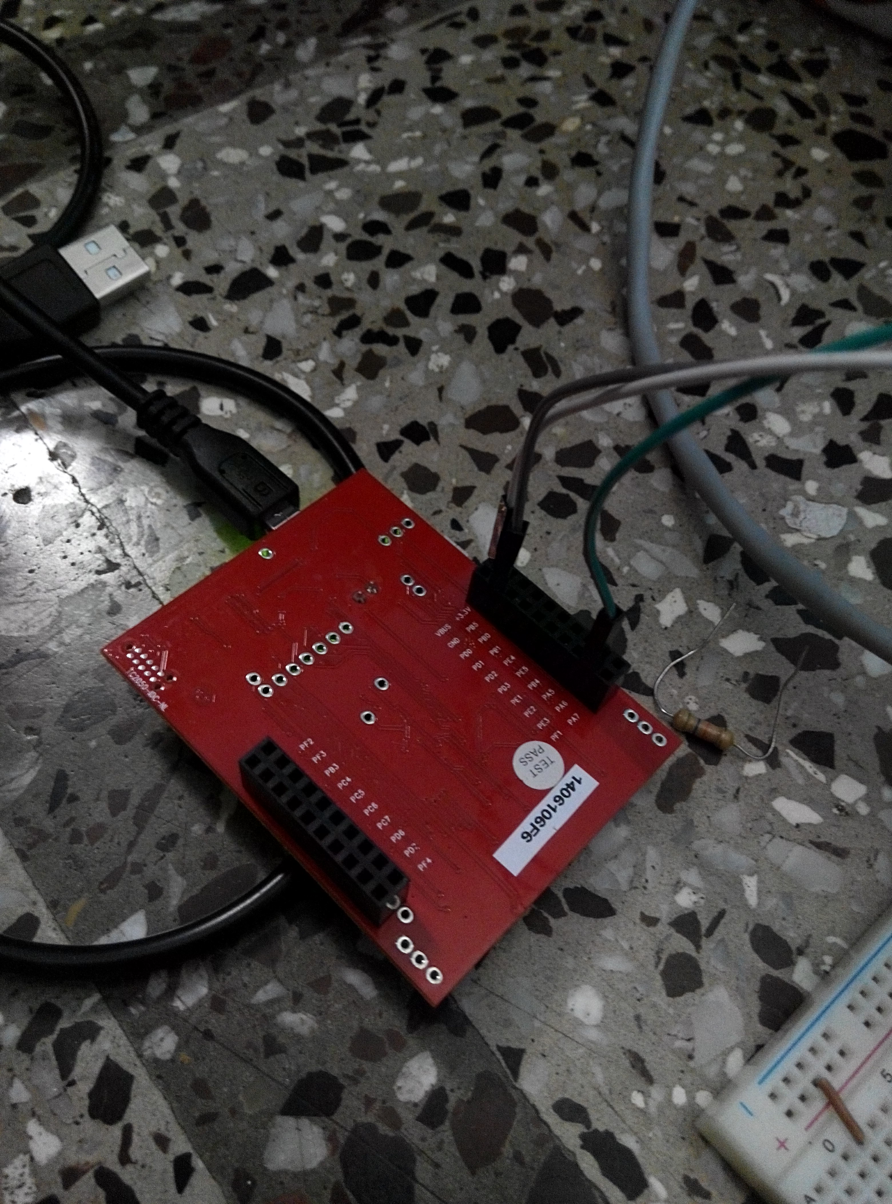
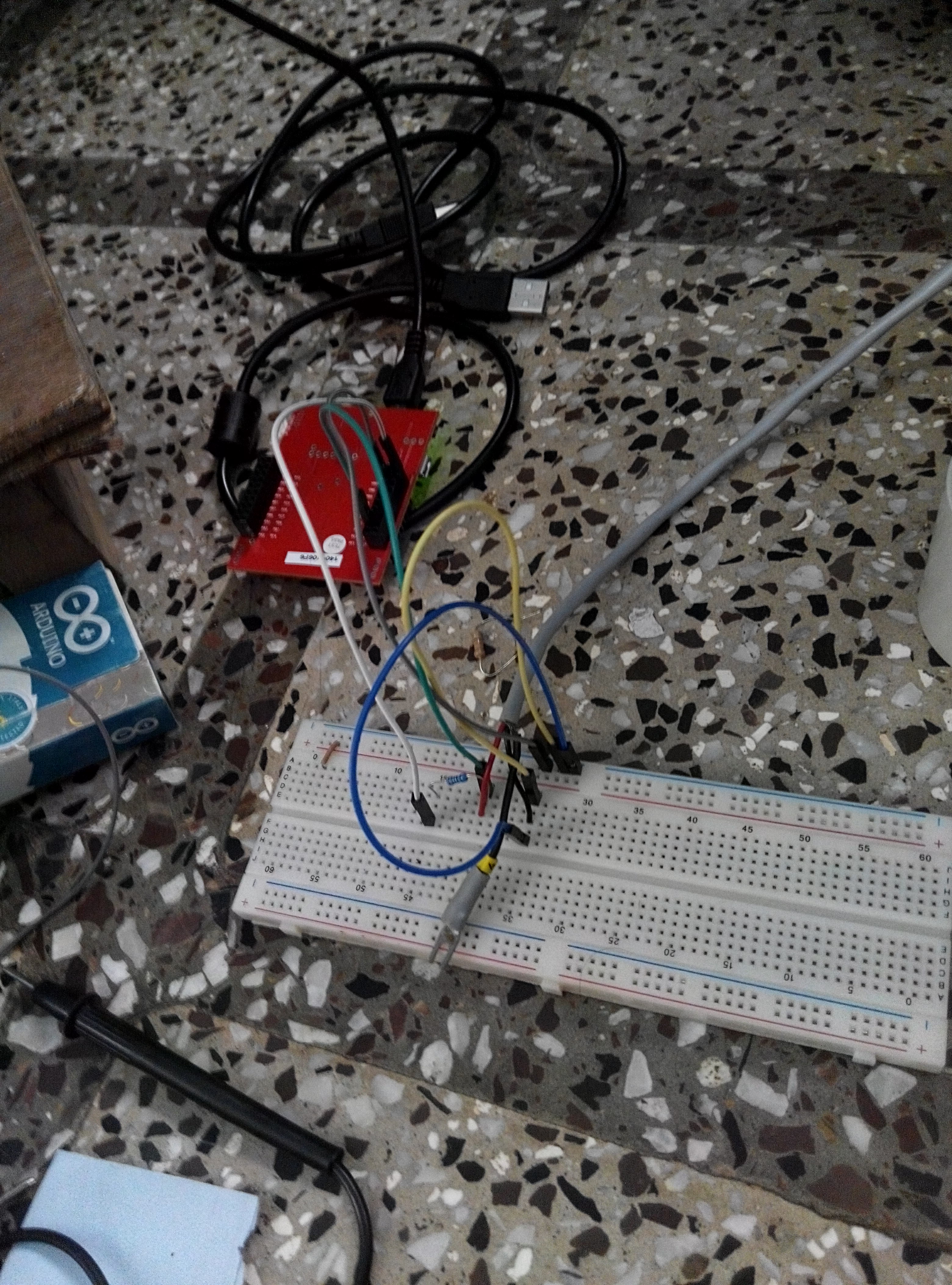
Board: TIVA-C Launchpad TM4C123GXL 

Sensor: PT1000 RTD, which has a resistance of 1000  Ohms at 0 degrees and increases by about 40 Ohms for a rise of 10 degrees, although not linearly and a lookup table is to be used to converting the resistance to temperature. Sensor is brand-new and is considered to be quite precise and durable with a stated accuracy of +/- 0.3 deg C and resolution of 0.1 Deg C. 

Now, trying to solve it simply (more complicated solution here), I am using a voltage divider with a 120 Ohm resistance in series. I am using the 3.3V output from board across the ends of this series and reading the voltage across the PT1000 sensor leads into the ADC pin with common grounds. 

Images of my setup at the end of the post. 

My code (written in Energia) 

// the setup routine runs once when you press reset:
void setup() {
  // initialize serial communication at 9600 bits per second:
  Serial.begin(9600); // msp430g2231 must use 4800
}

// the loop routine runs over and over again forever:
void loop() {
  // read the input on analog pin A3:
  int sensorValue = analogRead(A0);
  // print out the value you read:
  // The ADC Value
  Serial.println(sensorValue);
  // The voltage
  Serial.println(sensorValue*3.3*1000/4096);
  // The resistance of RTD
  Serial.println((sensorValue*3.3/4096)*120/(3.3 - (sensorValue*3.3/4096)));
  delay(1000); // delay in between reads for stability
}

And the output that I get, for small duration of time : 

R = 1111.88
ADC = 3702
Voltage *1000 = 2982.57
... 
R = 1127.51 ADC = 3701 Voltage * 1000 = 2981.76 1124.35 3695 2976.93 1105.74 3701 2981.76 1124.35 3699

As can be seen the value from the ADC, which should for the 12-bit TIVA-C ADC vary between 0-4095 fluctuates quite a bit (for not so much change in temperature). The voltage was multiplied by 1000 so that the fluctuations become more apparent. As a result the resistance varies by around 20 ohms, resulting in an overall accuracy of around 5 Degrees C. 

Is this is the best possible output accuracy using the current circuit ? What factors can be leading to these fluctuations? 

My board is being powered from my dell-laptop USB port using the provided cable. 

  • Your concern for MCU's ADC accuracy may benefit from:

    • MCUs are "mixed signal" devices - as such they cannot provide, "best/brightest" analog performance.   While 12 bits is specified - it has long been recognized that (most always) those 3 lsb will "bounce" and prove suspect.   (this is true for ALL ARM MCU vendors)
    • Your experimental-eased sensor set-up does not lead to the cleanest, most noise-free signal being fed to your MCU.   Short, direct signal introduction escapes much of the "unwanted noise" your photo depicts.
    • If you seek to monitor "away" from your MCU you may consider using a grounded, shielded cable to route the sensor's signal.
    • Should your MCU include Analog VDD & Analog Gnd - they should both be (properly) employed
    • Our firm (only) uses MCUs w/that separated Analog VDD - and we employ either a known, stable, reference voltage or a ferrite bead along with filter caps @ VDDA (which is fed by boards 3V3
    • A small cap - installed near your ADC input pin - should yield more stable readings

    Seems bit strange that you "challenge" the linearity of your PT1000 RTD.   Our belief is that these (being more expensive than thermistors) are most always chosen for their increased accuracy and linearity.   (linear over somewhat limited span)

  • The lookup table for PT1000 tends towards linearity with around 4 Ohm per degree, but I read somewhere, that the a lookup table is employed in place of a fixed equation since, the behavior is non-linear (though, quite predictable and repeatable).

    Our sensor has a long shielded cable alongwith it, and I am attaching that to the bread-board for primary testing, which I might later replace with soldered PCB.

    I am using Vdd and GND from the board itself.

    So, no software techniques like over-sampling can help in reducing the error ? ? (sampling rate isnt critical for me). I will try using a capacitor, and report back. :)

    Thanks.
  • Just one thing - breadboard = a heck of an radio antena - seriously it's noise galore on those things.

    Note also that "sensorValue*3.3/4096" will always give 0 with "sensorValue" bellow 1242.
  • Chintan Pathak4 said:
    So, no software techniques like over-sampling can help

    Indeed - over time you will reduce those lsb errors.   Yet - to "believe" you've achieved "real" 12 bit ADC performance... (I leave that to you)

    Unstated is how/why you "need" high accuracy temperature measures - AND how well located that RTD is - to the article being "temp. monitored."   We use RTDs - and even the size of the device influences "response time" (and unwanted "heating effects" caused by device powering.)

  • A couple of major points to start

    First, reading the micro's A/D specifications would show your results are within specification.
    Second, reading the RTD specifications would reveal you are overdriving the sensor. It would also show no resolution specification, such does not make sense for an analog sensor.

    Then you need to consider your signal conditioning details. The bare divider you have compresses the temperature signal.

    RTDs are nonlinear but the quadratic term is something like 4 orders of magnitude smaller than the linear. Enough to be significant at 100.

    You will want to move to a less noisy environment as others have pointed out, but I think the other issues are larger.

    However, absolutely the first thing you must do is define the temperature range, resolution and accuracy you require as a final result. And those are three distinct values.

    Robert
  • Robert Adsett72 said:
    It would also show no resolution specification, such does not make  sense for an analog sensor

    You won't run into quantum effects.

    Robert

  • Robert Adsett72 said:
    RTDs are nonlinear

    Strictly speaking that's true - but as you've noted - w/in the "real world" - and in a, "Piecewise, limited fashion" RTDs come damn close.  (to presenting a linear response)

    I know of no other device - w/in the RTDs size/price category (other than P-N junction - which has "issues") that provides a more linear response.   (especially when the drive circuitry & range of interest are well chosen & matched...)

    As poster has "ducked" the, "Requirement for accuracy" explanation - we (likely) are beating (another) dead horse...

  • We are going to be using this RTD for measurement of soil temperature. It has nice enclosure and is built for that purpose.  

    The accuracy afforded by the sensor is 0.1 Degree C, but I ouwld be fairly happy with even 1 Degree C accuracy. That translates to around 4 Ohms of resistance measurement.

  • The 10K in series with the PT1000 isn't really a divider with a temperature based output, it's a supply line sampler (ratio 1K/11K)with a temperature derived output mixed with it. Even if the PT1000 had completely stable 1K resistance at 0degC the output would still represent 1/11 of the supply, which has no definite value or guarantee what it will do. Yes, it's well damped by the 100uF, but it still samples the VCC rail.

    The 100uF has a leakage and may cause an input offset.

    The CD4052 is probably okay, but I've not looked at it.

    The LM324 opamp has an input offset voltage in the order of 2mV, and to further enhance the inaccuracy there's 2 of them feeding a differential amplifier with gain also with the same problem. Even if you joined the 2 inputs together (so intending zero diff amp output) you might see about 40mV-50mV (it's a guess) of output from the diff amp worse case. The 2nd voltage follower also has a supply line sampler for an input, except this time there's no damping on it. I would guess that the interaction of the RTD input divider and the divider on the 2nd voltage follower, and the resulting phase difference between their outputs, for what is essentially a common input, would also be enough to generate an reasonable output signal.

    Then there's a 220K feeding the ADC input which will likely introduce a significant offset into the ADC input.

    Things to look at.

    As some have already mentioned driving the RTD with too much current will cause it to self-heat. Drive the RTD with about 500uA or less, either with a precision current source or a stable current source and use a spare input to sample a precision resistor for a ratio comparison to an actual input.

    Get rid of the 100uF electrolytic capacitor, but bandwidth limitation is important for noise performance. Look at non-polarised capacitors for less leakage.

    Maybe ditch the voltage followers completely and look at 24bit delta sigma ADCs. You're only operating over a narrow input voltage swing and need far greater resolution than you might think. This will also give you a chance to divorce the ADC from the MCU and sort its power supply and reference out independently.

  • Actually having the signal vary with the power supply is likely a good thing, the A/D on most of these micros uses the power rail as its reference. Having the signal and reference vary in the same fashion makes for pretty reasonable accuracy.

    TI has a reasonable conditioning circuit for RTDs in one of their seminar notes.

    Robert
  • Hi,

    I have a problem like yours, but i've semplified the hardware in order to discover the problem.

    I have connectect my Analog Pin (PE_0) directly to GND and I perform a Serial.print( analogRead(PE_1) );

    The result (with 1000ms delay between each measure), are

    0 ; 0 ; 0 ; 0 ; 15 ; 0 ; 3 ;  0 ; 47 ; 0 ; 7;  0 ;  15 ; 0 ; 23 ; 0 ; 0 ; 0; ......

    It seems strange...

    I wish we can solve this problem fast, because i need this for a project in the next 4 days.

    Best regards,

    Francesco

  • Francesco Cencioni said:
    wish we can solve this problem fast, because i need this for a project in the next 4 days.

    And our wish - that you raised this issue far earlier.  (that said - at least you avoided the (always delightful) "urgent!")   None here caused/contributed to your "issue" - we should not be expected (now) to rush to your aid...

    ADCs w/in any vendors' MCU are not famed for high accuracy.   In our survey of similar MCUs (multiple vendors) the 3 lsb are most always "suspect."

    Your "47" reading is beyond 3 lsb - something must have been "out of bounds" during that measurement interval.   As always - your survey of "other" ADC channel inputs may improve results.

    To gain the best results from MCU's ADC it's often best to:

    • match the ADC's specified input resistance
    • employ a small cap to ground - as near to the MCU's ADC pin as possible
    • minimize signal length
    • avoid having the measurement signal come near switching, digital ones
    • try to limit the operation of high power switching and/or any RF emissions during the ADC measurement
  • Hello Francesco

    "I have connectect my Analog Pin (PE_0) directly to GND and I perform a Serial.print( analogRead(PE_1) );"

    Connected PE0 to GND and measured on PE1? while the other post from you

    e2e.ti.com/.../458823

    mentions PE1 to GND and measured on PE1...

    Regards
    Amit
  • Hi Amit,

    Thank you for your reply.

    PE_1 to GND and read from PE_1, it was only a bad typying.

    Regards,

    Francesco

  • Hello Francesco

    OK. Thanks for the clarification. We shall use your other post for all information exchange

    Regards
    Amit