Other Parts Discussed in Thread: ENERGIA
Hi,
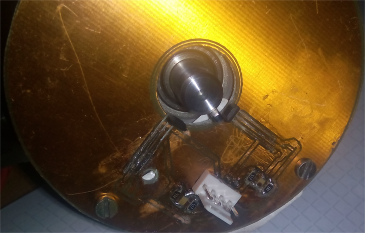
I want to use the QEI on my TM4C123GXL-Launchpad with two Hallsensors[Pic1] connected to PD6 and PD7.
The sensors output is 3.3V in normal state and 0V if the magnet passes. Thats why i invert the signals.
In CLOCK_DIR mode i see that position is counted if the magnet passes (2 counts each time) it works with both signals (tested by swapping PhA an PhB).
In QUADRATURE mode, the position counter doesn't work. Sometimes it +1 or -1 around the base value but it doesn't count the rotations...
I have unlocked PD7 and i think this works... (see clock_dir mode), the inversion works because the direction in clock_dir mode changes if i don't invert.
I hope someone can tell me what is wrong... Here is my code (I am using Energia):
#include <stdint.h>
#include <stdbool.h>

#include "inc/hw_gpio.h"
#include "inc/hw_ints.h"
#include "inc/hw_memmap.h"
#include "inc/hw_types.h"
#include "inc/hw_qei.h"

#include "driverlib/gpio.h"
#define PART_TM4C123GH6PM
#include "driverlib/pin_map.h"
#include "driverlib/qei.h"
#include "driverlib/sysctl.h"


//*****************************************************************************

//

// Configuration of the QEI

//

//*****************************************************************************
void config_QEI()
{


  // Enable QEI Peripherals
  SysCtlPeripheralEnable(SYSCTL_PERIPH_GPIOD);
  SysCtlPeripheralEnable(SYSCTL_PERIPH_QEI0);

  //Unlock GPIOD7
  HWREG(GPIO_PORTD_BASE + GPIO_O_LOCK) = GPIO_LOCK_KEY;
  HWREG(GPIO_PORTD_BASE + GPIO_O_CR) |= 0x80;
  HWREG(GPIO_PORTD_BASE + GPIO_O_AFSEL) &= ~0x80;
  HWREG(GPIO_PORTD_BASE + GPIO_O_DEN) |= 0x80;
  HWREG(GPIO_PORTD_BASE + GPIO_O_LOCK) = 0;

  //Set Pins to be PHA0 and PHB0
  GPIOPinConfigure(GPIO_PD6_PHA0); //GPIOPinConfigure(0x00031806);  //0x00031806 =>GPIO_PD6_PHA0
  GPIOPinConfigure(GPIO_PD7_PHB0); //GPIOPinConfigure(0x00031C06);  // 0x00031C06 => GPIO_PD7_PHB0

  //Set GPIO pins for QEI
  GPIOPinTypeQEI(GPIO_PORTD_BASE, (GPIO_PIN_6 | GPIO_PIN_7));

  // Configure quadrature encoder, use an arbitrary top limit of 2000 and enable QEI
  QEIConfigure(QEI0_BASE,(QEI_CONFIG_CAPTURE_A_B | QEI_CONFIG_NO_RESET | QEI_CONFIG_QUADRATURE | QEI_CONFIG_NO_SWAP | QEI_CTL_INVA | QEI_CTL_INVB), 10000);
  QEIEnable(QEI0_BASE);

  //Set starting position, non zero
  QEIPositionSet(QEI0_BASE, 1000);

  //Configure and enable velocity
  QEIVelocityConfigure(QEI0_BASE, QEI_VELDIV_1, SysCtlClockGet()); // Divide by clock speed to get counts/sec
  QEIVelocityEnable(QEI0_BASE);

}
void setup()
{
  config_QEI();
  Serial.begin(9600);
  Serial.println("Start:");
  Serial.println("--------");
}

void loop()
{
  uint32_t velocity, position;
  int32_t rotatingdirection;

  position = QEIPositionGet(QEI0_BASE);
  velocity = QEIVelocityGet(QEI0_BASE);
  rotatingdirection = QEIDirectionGet(QEI0_BASE);

  Serial.println(position);
  Serial.println(velocity);
  Serial.println(rotatingdirection);
  Serial.println("--------");
  delay(1000);

}
Pic1: