


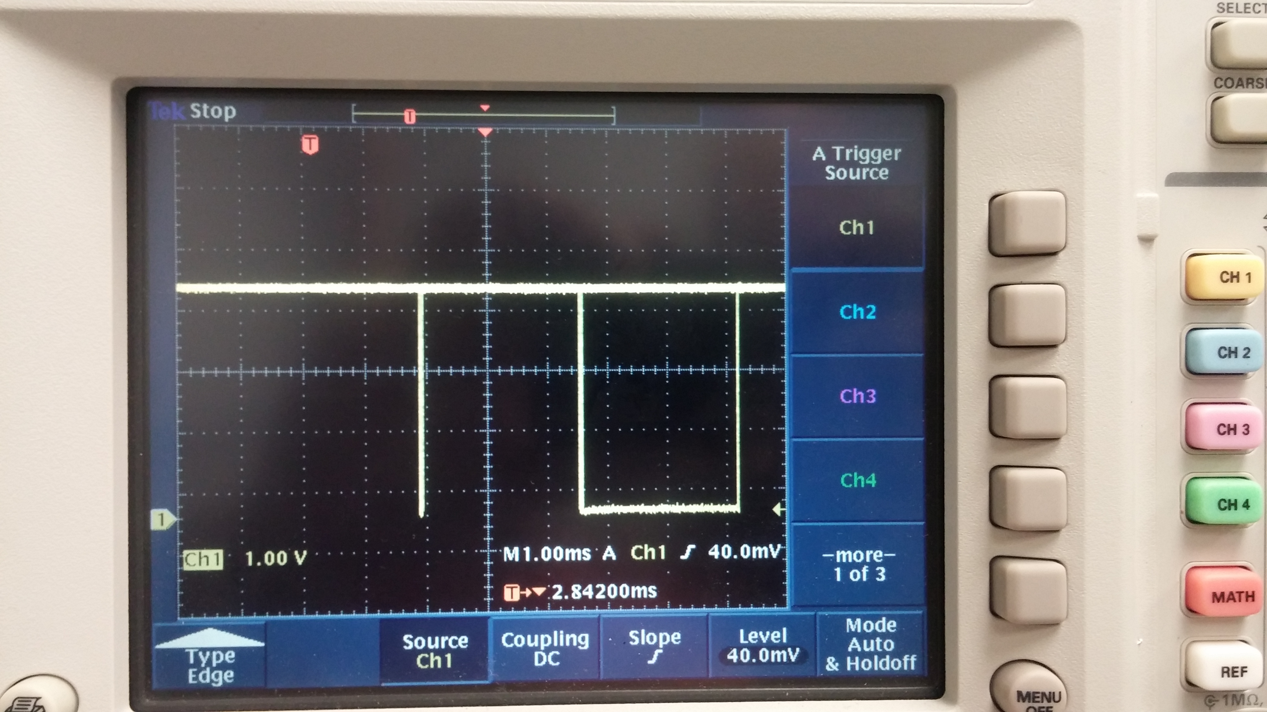
I'm working on connecting a few I2C chips to my TM4C129X EK board, so far I am able to get output but the output isn't what I am expecting. In the case of the MCP4725 chip I am seeing some behavior in the clock line that I am not expecting, A picture of the oscilloscope reading is attached, and the code I am using is below that (partially borrowed from another post). The VOUT line and the SDA line also appear to be reading 0. Any advice or help would be appreciated!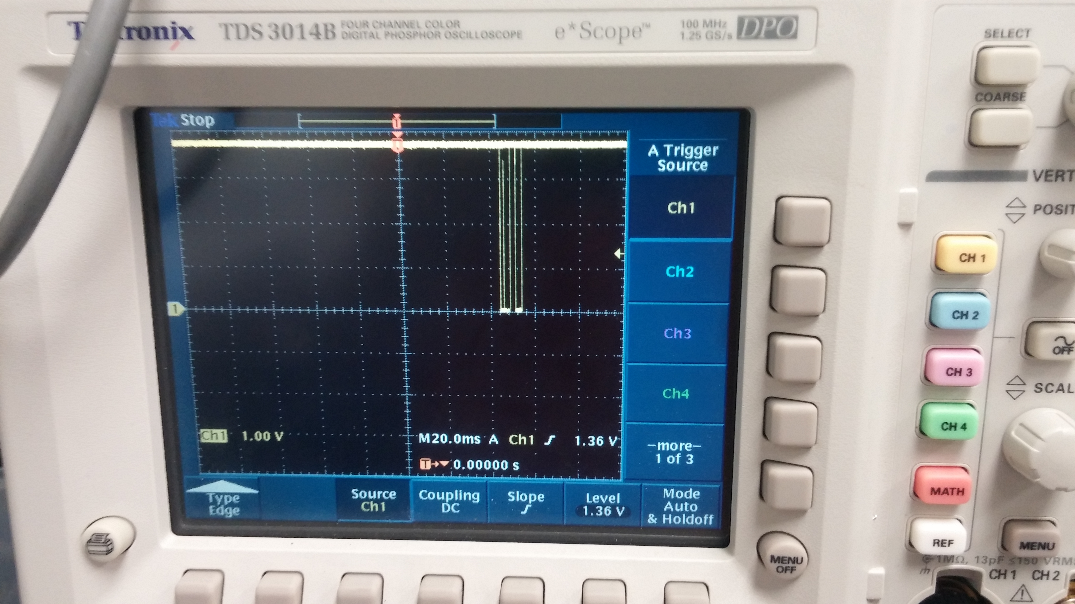
#include <stdbool.h>
#include <stdint.h>
#include "inc/hw_i2c.h"
#include "inc/hw_ints.h"
#include "inc/hw_memmap.h"
#include "inc/hw_types.h"
#include "driverlib/gpio.h"
#include "driverlib/i2c.h"
#include "driverlib/interrupt.h"
#include "driverlib/pin_map.h"
#include "driverlib/sysctl.h"
#include "driverlib/uart.h"
#include "utils/uartstdio.h"
#include "driverlib/rom_map.h"
#include "inc/hw_types.h"
#include "inc/hw_gpio.h"

uint32_t ui32SysClock;
volatile uint8_t data[10];

//const uint8_t INA219address = 0x40;

const uint8_t MCP4725address = 0x62;
const bool DebuggingMode = true;


void InitConsole(void)
{
    SysCtlPeripheralEnable(SYSCTL_PERIPH_GPIOA);
    GPIOPinConfigure(GPIO_PA0_U0RX);
    GPIOPinConfigure(GPIO_PA1_U0TX);
    SysCtlPeripheralEnable(SYSCTL_PERIPH_UART0);
    UARTClockSourceSet(UART0_BASE, UART_CLOCK_PIOSC);
    GPIOPinTypeUART(GPIO_PORTA_BASE, GPIO_PIN_0 | GPIO_PIN_1);
    UARTStdioConfig(0, 115200, 16000000);
}


void i2c0_init()
{
       MAP_SysCtlPeripheralEnable(SYSCTL_PERIPH_I2C0);
       MAP_SysCtlPeripheralEnable(SYSCTL_PERIPH_GPIOB);

       MAP_GPIOPinTypeI2C(GPIO_PORTB_BASE, GPIO_PIN_3);
       MAP_GPIOPinConfigure(GPIO_PB3_I2C0SDA);

       MAP_GPIOPinTypeI2CSCL(GPIO_PORTB_BASE, GPIO_PIN_2);
       MAP_GPIOPinConfigure(GPIO_PB2_I2C0SCL);

       I2CMasterInitExpClk(I2C0_BASE, ui32SysClock, false);
              while (I2CMasterBusy(I2C0_BASE));
       if (DebuggingMode) UARTprintf("\n Initializing I2C0 -> Error: %u ",I2CMasterErr(I2C0_BASE));

}

uint32_t i2c0_write(uint8_t addr, uint8_t *value, uint8_t N)
{
    uint32_t error = { 0 };
    uint8_t i;
    I2CMasterSlaveAddrSet(I2C0_BASE, addr, false);
if(N==1){
//    I2CMasterSlaveAddrSet(I2C0_BASE, addr>>1, false);
    //I2CMasterSlaveAddrSet(I2C0_BASE, addr, false);
      // while (I2CMasterBusy(I2C0_BASE));
    I2CMasterDataPut(I2C0_BASE, value);
       //while (I2CMasterBusy(I2C0_BASE));
    I2CMasterControl(I2C0_BASE, I2C_MASTER_CMD_SINGLE_SEND);
       while (I2CMasterBusy(I2C0_BASE));
    if (DebuggingMode) UARTprintf("\n Sending data(%X) -> Error: %u ",value, I2CMasterErr(I2C0_BASE));
}
else{
    I2CMasterDataPut(I2C0_BASE, value[0]);
           while (I2CMasterBusBusy(I2C0_BASE));
    I2CMasterControl(I2C0_BASE, I2C_MASTER_CMD_BURST_SEND_START);
           while (I2CMasterBusy(I2C0_BASE));
    //TODO change this to a try catch or something
    if (DebuggingMode) UARTprintf("\n Reading data(%X) -> Error: %u ",value[0], I2CMasterErr(I2C0_BASE));

    for (i=1;i<(N-1);i++)
    {
    	 I2CMasterDataPut(I2C0_BASE, value[i]);
             //while (I2CMasterBusy(I2C0_BASE));
           I2CMasterControl(I2C0_BASE, I2C_MASTER_CMD_BURST_SEND_CONT);
                 while (I2CMasterBusy(I2C0_BASE));
           if (DebuggingMode) UARTprintf("\n Reading data(%X) -> Error: %u ",value[i], I2CMasterErr(I2C0_BASE));
    }

   I2CMasterDataPut(I2C0_BASE, value[N-1]);
          //while (I2CMasterBusy(I2C0_BASE));
    I2CMasterControl(I2C0_BASE, I2C_MASTER_CMD_BURST_SEND_FINISH);
           while (I2CMasterBusy(I2C0_BASE));
    if (DebuggingMode) UARTprintf("\n Reading data(%X) -> Error: %u ", value[N-1], I2CMasterErr(I2C0_BASE));
}

    return I2CMasterErr(I2C0_BASE);
}

void i2c0_read(uint8_t addr, uint8_t *RxData, uint8_t N)
{
       uint8_t i;

//       I2CMasterSlaveAddrSet(I2C0_BASE, addr>>1, true);
       I2CMasterSlaveAddrSet(I2C0_BASE, addr, true);
              while (I2CMasterBusBusy(I2C0_BASE));

       if (N==1)
       {
              I2CMasterControl(I2C0_BASE, I2C_MASTER_CMD_SINGLE_RECEIVE);
                     while (I2CMasterBusy(I2C0_BASE));
              RxData[0]=I2CMasterDataGet(I2C0_BASE);
                     while (I2CMasterBusy(I2C0_BASE));
              if (DebuggingMode) UARTprintf("\n Reading data(%X) -> Error: %u ",RxData[0], I2CMasterErr(I2C0_BASE));
       }
       else
       {
              I2CMasterControl(I2C0_BASE, I2C_MASTER_CMD_BURST_RECEIVE_START);
                     while (I2CMasterBusy(I2C0_BASE));
              RxData[0]=I2CMasterDataGet(I2C0_BASE);
                     while (I2CMasterBusy(I2C0_BASE));
              //TODO change this to a try catch or something
              if (DebuggingMode) UARTprintf("\n Reading data(%X) -> Error: %u ",RxData[0], I2CMasterErr(I2C0_BASE));

              for (i=1;i<(N-1);i++)
              {
                     I2CMasterControl(I2C0_BASE, I2C_MASTER_CMD_BURST_RECEIVE_CONT);
                           while (I2CMasterBusy(I2C0_BASE));
                     RxData[i]=I2CMasterDataGet(I2C0_BASE);
                           while (I2CMasterBusy(I2C0_BASE));
                     if (DebuggingMode) UARTprintf("\n Reading data(%X) -> Error: %u ",RxData[i], I2CMasterErr(I2C0_BASE));
              }

              I2CMasterControl(I2C0_BASE, I2C_MASTER_CMD_BURST_RECEIVE_FINISH);
                     while (I2CMasterBusy(I2C0_BASE));
              RxData[N-1]=I2CMasterDataGet(I2C0_BASE);
                     while (I2CMasterBusy(I2C0_BASE));
              if (DebuggingMode) UARTprintf("\n Reading data(%X) -> Error: %u ",RxData[N-1], I2CMasterErr(I2C0_BASE));
       }
}


int
main(void)
{
	MAP_SysCtlClockFreqSet((SYSCTL_XTAL_25MHZ | SYSCTL_OSC_MAIN |
	     	SYSCTL_USE_PLL |
	     	SYSCTL_CFG_VCO_320), 16000000);

              MAP_SysCtlPeripheralEnable(SYSCTL_PERIPH_GPION);
              MAP_GPIOPinTypeGPIOOutput(GPIO_PORTN_BASE,GPIO_PIN_0 | GPIO_PIN_1);

              GPIOPinWrite(GPIO_PORTN_BASE,GPIO_PIN_0,0);
              GPIOPinWrite(GPIO_PORTN_BASE,GPIO_PIN_1,0);

              InitConsole();
              i2c0_init();


        uint8_t Rx[2]={0,0};
        uint8_t Tx[4] = {0,0,0,0};
        uint32_t i;
        uint32_t index = 120000000/8;	// Produces an approximately 1 sec

        //SEt the register to read

        while(1){
        	Tx[0]= MCP4725address;
        	Tx[1] = 64;
        	Tx[2] = 8;
        	Tx[3] = 0;
            i2c0_write(MCP4725address, Tx, 3);
//            //read Shunt Voltage one time
            Rx[0] = 0;
            Rx[1] = 0;
            // Read the data
            i2c0_read(MCP4725address,Rx,2);
            int shuntVoltage = Rx[0]*256+Rx[1];
            UARTprintf("\n ");
            UARTprintf("\n Shunt Voltage: %i ",shuntVoltage);
            UARTprintf("\n ");
            UARTprintf("*************************************************\n ");


	//poor mans delay
           for (i=0;i<index;i++){
            	//Wait for 120000000 Cnts
            }

        }

}

