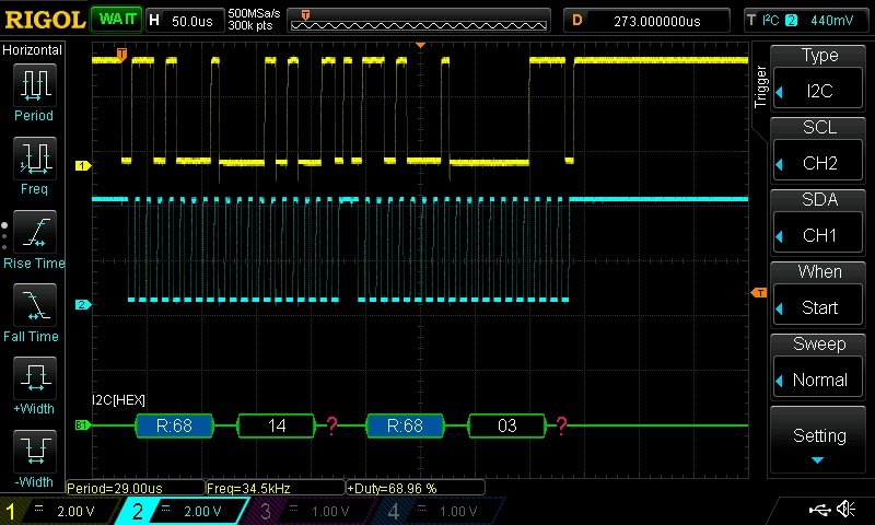
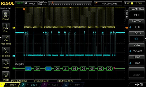
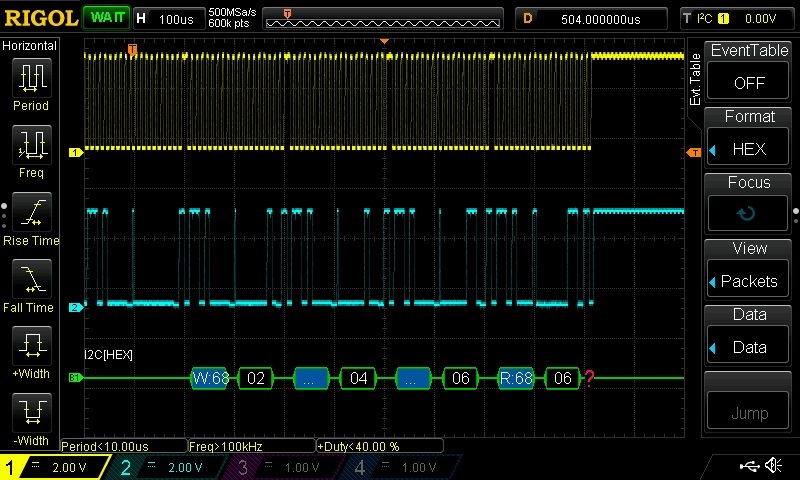
Hi, i'm working with a TM4C1294XL board and a DS1307 board from grove. I found scratch of code in a website and i adapted it for my MCU. The program compiles wothout errors or warnings, the problem is the data read from RTC. When the program prints data on the UART, every print is different from the setup value, and non increase, are "random" numbers. I can't found where the problem is. i post the code and a screen from Oscilloscope when the function SetTimeDate(30,32,8,4,5,11,14); is called. Thanks in advance for your support.
//include files
 #include <stdarg.h>
 #include <stdbool.h>
 #include <stdint.h>
 #include "inc/hw_i2c.h"
 #include "inc/hw_memmap.h"
 #include "inc/hw_types.h"
 #include "inc/hw_gpio.h"
 #include "driverlib/i2c.h"
 #include "driverlib/sysctl.h"
 #include "driverlib/gpio.h"
 #include "driverlib/pin_map.h"
 #include "driverlib/uart.h"
 #include "utils/uartstdio.h"
 //Defines for DS1307
 #define SLAVE_ADDRESS 0x68
 #define SEC 0x00
 #define MIN 0x01
 #define HRS 0x02
 #define DAY 0x03
 #define DATE 0x04
 #define MONTH 0x05
 #define YEAR 0x06
 #define CNTRL 0x07

uint32_t g_ui32SysClock;

 //initialize I2C module 0
 //Slightly modified version of TI's example code
 void InitI2C0(void)
 {
   //enable I2C module 0
   SysCtlPeripheralEnable(SYSCTL_PERIPH_I2C0);
   //reset module
   SysCtlPeripheralReset(SYSCTL_PERIPH_I2C0);
   //enable GPIO peripheral that contains I2C 0
   SysCtlPeripheralEnable(SYSCTL_PERIPH_GPIOB);
   // Configure the pin muxing for I2C0 functions on port B2 and B3.
   GPIOPinConfigure(GPIO_PB2_I2C0SCL);
   GPIOPinConfigure(GPIO_PB3_I2C0SDA);

   // Select the I2C function for these pins.
   GPIOPinTypeI2CSCL(GPIO_PORTB_BASE, GPIO_PIN_2);
   GPIOPinTypeI2C(GPIO_PORTB_BASE, GPIO_PIN_3);
   I2CTxFIFOConfigSet(I2C0_BASE, I2C_FIFO_CFG_TX_MASTER);

   // Enable and initialize the I2C0 master module. Use the system clock for
   // the I2C0 module. The last parameter sets the I2C data transfer rate.
   // If false the data rate is set to 100kbps and if true the data rate will
   // be set to 400kbps.
   I2CMasterInitExpClk(I2C0_BASE, g_ui32SysClock, false);
   //clear I2C FIFOs
   //HWREG(I2C0_BASE + I2C_O_FIFOCTL) = 80008000;
   I2CRxFIFOFlush(I2C0_BASE);
   I2CTxFIFOFlush(I2C0_BASE);
 }
 //sends an I2C command to the specified slave
 void I2CSend(uint8_t slave_addr, uint8_t num_of_args, ...)
 {
   // Tell the master module what address it will place on the bus when
   // communicating with the slave.
   I2CMasterSlaveAddrSet(I2C0_BASE, slave_addr, false);
   //stores list of variable number of arguments
   va_list vargs;
   //specifies the va_list to "open" and the last fixed argument
   //so vargs knows where to start looking
   va_start(vargs, num_of_args);
   //put data to be sent into FIFO
   I2CMasterDataPut(I2C0_BASE, va_arg(vargs, uint32_t));
   //if there is only one argument, we only need to use the
   //single send I2C function
   if(num_of_args == 1)
   {
     //Initiate send of data from the MCU
     I2CMasterControl(I2C0_BASE, I2C_MASTER_CMD_SINGLE_SEND);
     // Wait until MCU is done transferring.
     while(I2CMasterBusy(I2C0_BASE));
     //"close" variable argument list
     va_end(vargs);
   }
   //otherwise, we start transmission of multiple bytes on the
   //I2C bus
   else
   {
     //Initiate send of data from the MCU
     I2CMasterControl(I2C0_BASE, I2C_MASTER_CMD_BURST_SEND_START);
     // Wait until MCU is done transferring.
     while(I2CMasterBusy(I2C0_BASE));
     //send num_of_args-2 pieces of data, using the
     //BURST_SEND_CONT command of the I2C module
     unsigned char i;
     for(i = 1; i < (num_of_args - 1); i++)
     {
       //put next piece of data into I2C FIFO
       I2CMasterDataPut(I2C0_BASE, va_arg(vargs, uint32_t));
       //send next data that was just placed into FIFO
       I2CMasterControl(I2C0_BASE, I2C_MASTER_CMD_BURST_SEND_CONT);
       // Wait until MCU is done transferring.
       while(I2CMasterBusy(I2C0_BASE));
     }
     //put last piece of data into I2C FIFO
     I2CMasterDataPut(I2C0_BASE, va_arg(vargs, uint32_t));
     //send next data that was just placed into FIFO
     I2CMasterControl(I2C0_BASE, I2C_MASTER_CMD_BURST_SEND_FINISH);
     // Wait until MCU is done transferring.
     while(I2CMasterBusy(I2C0_BASE));
     //"close" variable args list
     va_end(vargs);
   }
 }

 //read specified register on slave device
 uint32_t I2CReceive(uint32_t slave_addr, uint8_t reg)
 {
   //specify that we are writing (a register address) to the
   //slave device
   I2CMasterSlaveAddrSet(I2C0_BASE, slave_addr, false);
   //specify register to be read
   I2CMasterDataPut(I2C0_BASE, reg);
   //send control byte and register address byte to slave device
   I2CMasterControl(I2C0_BASE, I2C_MASTER_CMD_BURST_SEND_START);
   //wait for MCU to finish transaction
   while(I2CMasterBusy(I2C0_BASE));
   //specify that we are going to read from slave device
   I2CMasterSlaveAddrSet(I2C0_BASE, slave_addr, true);
   //send control byte and read from the register we
   //specified
   I2CMasterControl(I2C0_BASE, I2C_MASTER_CMD_SINGLE_RECEIVE);
   //wait for MCU to finish transaction
   while(I2CMasterBusy(I2C0_BASE));
   //return data pulled from the specified register
   return I2CMasterDataGet(I2C0_BASE);
 }
 //convert dec to bcd
 unsigned char dec2bcd(unsigned char val)
 {
      return (((val / 10) << 4) | (val % 10));
 }
 // convert BCD to binary
 unsigned char bcd2dec(unsigned char val)
 {
  return (((val & 0xF0) >> 4) * 10) + (val & 0x0F);
 }
 //Set Time
 void SetTimeDate(unsigned char sec, unsigned char min, unsigned char hour,unsigned char day, unsigned char date, unsigned char month,unsigned char year)
 {
      I2CSend(SLAVE_ADDRESS,8,SEC,dec2bcd(sec),dec2bcd(min),dec2bcd(hour),dec2bcd(day),dec2bcd(date),dec2bcd(month),dec2bcd(year));
 }

 //Get Time and Date
 unsigned char GetClock(unsigned char reg)
 {
      unsigned char clockData = I2CReceive(SLAVE_ADDRESS,reg);
      return bcd2dec(clockData);
      //return clockData;
 }
 void ConfigureUART(void)
 {
	    // Enable the GPIO Peripheral used by the UART.
	    SysCtlPeripheralEnable(SYSCTL_PERIPH_GPIOA);
	 // Enable UART0.
	    SysCtlPeripheralEnable(SYSCTL_PERIPH_UART0);

	    // Configure GPIO Pins for UART mode.
	    GPIOPinConfigure(GPIO_PA0_U0RX);
	    GPIOPinConfigure(GPIO_PA1_U0TX);
	    GPIOPinTypeUART(GPIO_PORTA_BASE, GPIO_PIN_0 | GPIO_PIN_1);

	    // Initialize the UART for console I/O.
	    UARTStdioConfig(0, 115200, g_ui32SysClock);

 }
 void main(void)
 {
      // Set the clocking to run directly from the external crystal/oscillator.
	 g_ui32SysClock = SysCtlClockFreqSet((	SYSCTL_XTAL_25MHZ |
	 						SYSCTL_OSC_MAIN   |
	 						SYSCTL_USE_PLL 	  |
	 						SYSCTL_CFG_VCO_480), 120000000);

        //initialize I2C module 0
        InitI2C0();
        ConfigureUART();
        SetTimeDate(30,32,8,4,5,11,14);
        unsigned char sec,min,hour,day,date,month,year;
        while(1)
        {
             sec = GetClock(SEC);
             min = GetClock(MIN);
             hour = GetClock(HRS);
             day = GetClock(DAY);
             date = GetClock(DATE);
             month = GetClock(MONTH);
             year = GetClock(YEAR);

             UARTprintf("%02d:%02d:%02d \n%02d %02d/%02d/%02d\n",hour,min,sec,day,date,month,year);

            SysCtlDelay(g_ui32SysClock);
        }
 }


