This thread has been locked.

If you have a related question, please click the "Ask a related question" button in the top right corner. The newly created question will be automatically linked to this question.

TivaWare Peripheral Driver Library for EK-TM4C129EXL - GPIO Example Does Not Work

Other Parts Discussed in Thread: EK-TM4C129EXL, TM4C1294NCPDT, EK-TM4C1294XL, LMFLASHPROGRAMMER

I purchased a EK-TM4C129EXL board 3 days ago and have not been able to drive GPIO using the Peripheral Driver Library ONLY!

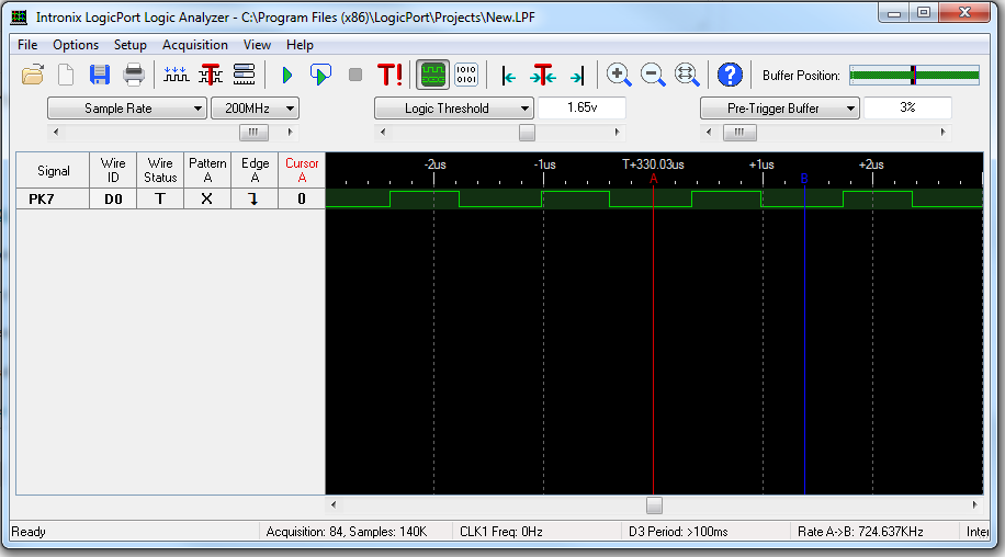
I can get the "blinky" example to drive hardware outputs to view on a scope and I understand the direct register use.

Using the GPIO Driver Library I cannot get the same hardware output to work. The Driver Library User Guide has a GPIO example which DOES NOT WORK.

Does anyone have a useful example of using Driver Library GPIO inputs and outputs and all configuration steps.?

The TivaWare examples are all over the place and are not very helpful. A simple GPIO Driver example would have been all that I needed to do this myself.

  • Hello Mark,

    Can you please share the GPIO example code which you are using the Peripheral Driver Library?

    Regards
    Amit
  • Amit,

    This is copied directly from Section 15.3 of TivaWare™ Peripheral Driver Library User Guide.

    There is no initialization code here or in any example project that I can find!! One difference is I am using PORT K for physical test point convenience. I can get PORT K to work with "blinky" direct register example.


    int32_t i32Val;
    //
    // Register the port-level interrupt handler. This handler is the first
    // level interrupt handler for all the pin interrupts.
    //
    GPIOIntRegister(GPIO_PORTA_BASE, PortAIntHandler);
    //
    // Initialize the GPIO pin configuration.
    //
    // Set pins 2, 4, and 5 as input, SW controlled.
    //
    GPIOPinTypeGPIOInput(GPIO_PORTA_BASE,
    GPIO_PIN_2 | GPIO_PIN_4 | GPIO_PIN_5);
    //
    // Set pins 0 and 3 as output, SW controlled.
    //
    GPIOPinTypeGPIOOutput(GPIO_PORTA_BASE, GPIO_PIN_0 | GPIO_PIN_3);
    //
    // Make pins 2 and 4 rising edge triggered interrupts.
    //
    GPIOIntTypeSet(GPIO_PORTA_BASE, GPIO_PIN_2 | GPIO_PIN_4, GPIO_RISING_EDGE);
    //
    // Make pin 5 high level triggered interrupts.
    //
    GPIOIntTypeSet(GPIO_PORTA_BASE, GPIO_PIN_5, GPIO_HIGH_LEVEL);
    //
    // Read some pins.
    //
    i32Val = GPIOPinRead(GPIO_PORTA_BASE,
    (GPIO_PIN_0 | GPIO_PIN_2 | GPIO_PIN_3 |
    GPIO_PIN_4 | GPIO_PIN_5));
    //
    // Write some pins. Even though pins 2, 4, and 5 are specified, those pins
    // are unaffected by this write because they are configured as inputs. At
    // the end of this write, pin 0 is low, and pin 3 is high.
    //
    GPIOPinWrite(GPIO_PORTA_BASE,
    (GPIO_PIN_0 | GPIO_PIN_2 | GPIO_PIN_3 |
    GPIO_PIN_4 | GPIO_PIN_5),
    (GPIO_PIN_3 | GPIO_PIN_4 | GPIO_PIN_5 | GPIO_PIN_6 |
    GPIO_PIN_7));
    //
    // Enable the pin interrupts.
    //
    GPIOIntEnable(GPIO_PORTA_BASE, GPIO_PIN_2 | GPIO_PIN_4 | GPIO_PIN_5);
  • I should add - what good are examples that do not work as published?
  • Hello Mark,

    The first step before programming any module is calling the enable function to start the clock.

    1. SysCtlPeripheralEnable with the argument of the peripheral being enabled, in this case it is SYSCTL_PERIPH_GPIOA

    the next step is to ensure that the interrupt handler is initialized ( I do not the see interrupt handler PortAIntHandler) in the code post (again arguably because it was not there in the document).

    Once all the code is in place and the code is executed, then halted, where the code execution show in the IDE?

    Regards
    Amit
  • Here is the actual test code which has the SysCtlPeripheralEnable call and it does not work. The Code Composer IDE Debug falls into the loop with no output on Pin 7 of Port K.

    #include <stdint.h>
    #include <stdbool.h>
    #include "inc/hw_ints.h"
    #include "inc/hw_memmap.h"
    #include "driverlib/gpio.h"
    #include "driverlib/sysctl.h"

    int
    main(void)
    {
    //Configure Port K Pin 7
    SysCtlPeripheralEnable(SYSCTL_PERIPH_GPIOK);
    GPIOPinTypeGPIOOutput(GPIO_PORTK_BASE, GPIO_PIN_7);

    //Control Loop
    while(1)
    {
    GPIOPinWrite(GPIO_PORTK_BASE, GPIO_PIN_7, 1);
    GPIOPinWrite(GPIO_PORTK_BASE, GPIO_PIN_7, 0);
    }
    }


    Here is the "blinky" example project code which does work.

    #include <stdint.h>
    #include <stdbool.h>
    #include "inc/tm4c1294ncpdt.h"
    #include "inc/hw_memmap.h"

    int
    main(void)
    {
    //Configure Port K Pin 7
    SYSCTL_RCGCGPIO_R = SYSCTL_RCGCGPIO_R9;
    GPIO_PORTK_DIR_R = 0x80;
    GPIO_PORTK_DEN_R = 0x80;

    while(1)
    {
    GPIO_PORTK_DATA_R = 0x80;
    GPIO_PORTK_DATA_R = 0x7F;
    }
    }
  • Hello Mark,

    If you check the example code the GPIOPinWrite API does not use 0 or 1 to clear or set but the pin number. This may seem strange but due to the fact the GPIO Port Pin are in bit banded address space, it is possible to write to a pin w/o affecting the state of other pins

    GPIOPinWrite(GPIO_PORTK_BASE, GPIO_PIN_7, GPIO_PIN_7,);
    GPIOPinWrite(GPIO_PORTK_BASE, GPIO_PIN_7, 0);

    Regards
    Amit
  • I just tried that and it still does not work!
  • Hello Mark

    Port K7 does not have a LED. The blinky code is for Port N0.

    Regards
    Amit
  • No. Look at my modifications in the blinky code example I sent along with my driver example. Both are using Port K - Pin 7
  • Hello Mark

    So you have connected the PK7 to the LED. Is that a correct statement? I did a modification on the EK-TM4C1294XL and the following code does work

    //Configure Port K Pin 7
    SysCtlPeripheralEnable(SYSCTL_PERIPH_GPIOK);
    GPIOPinTypeGPIOOutput(GPIO_PORTK_BASE, GPIO_PIN_7);

    //Control Loop
    while(1)
    {
    GPIOPinWrite(GPIO_PORTK_BASE, GPIO_PIN_7, GPIO_PIN_7);
    GPIOPinWrite(GPIO_PORTK_BASE, GPIO_PIN_7, 0);
    }

    Regards
    Amit
  • I have an ocsilloscope probe on Port K - Pin 7 - there is NO LED connection. I have a EK-TMC4129EXL does that make any difference. The driver library code does not work is all I know.
  • I can download the modified blinky example that I showed you and the Port K - Pin 7 shows the waveform I expect. I download the driver library example and Port K - Pin 7 is 0 Volts.
  • Hello Mark,

    I switched to EK-TM4C129EXL as well and it works. Attached is a LA snapshot for the same

    Regards

    Amit

  • My unit arrived 3 days ago. Have there been any firmware changes recently and your unit is older?

    As i stated, the direct register method works (modified blink code) and the driver method does not. I can download the .bin files and test each method without touching the physical test setup.

    What do I do next?
  • Hello Mark

    No. There have been no firmware changes, especially when it comes to the peripherals.

    Something to try for sure is to now debug why the code is behaving in such a manner. Use the step function to see what the CPU does when using the GPIOPinWrite call. At the same time in the debugger open the GPIO register view to see how the GPIO registers get updated. I am kind of surprised.

    As the last try you can use the bin file that I have been flashing. If you have the LMFlashProgrammer installed on your PC, then you can flash the bin file via the same.

    https://e2e.ti.com/cfs-file/__key/communityserver-discussions-components-files/908/tm4c_5F00_all_5F00_led_5F00_blink.bin

    Regards

    Amit

  • Your bin file works. Please send me your source file!
  • Hello Mark,

    Sure. Attached in the post

    //*****************************************************************************
    //
    //
    // Copyright (c) 2011-2015 Texas Instruments Incorporated.  All rights reserved.
    // Software License Agreement
    // 
    // Texas Instruments (TI) is supplying this software for use solely and
    // exclusively on TI's microcontroller products. The software is owned by
    // TI and/or its suppliers, and is protected under applicable copyright
    // laws. You may not combine this software with "viral" open-source
    // software in order to form a larger program.
    // 
    // THIS SOFTWARE IS PROVIDED "AS IS" AND WITH ALL FAULTS.
    // NO WARRANTIES, WHETHER EXPRESS, IMPLIED OR STATUTORY, INCLUDING, BUT
    // NOT LIMITED TO, IMPLIED WARRANTIES OF MERCHANTABILITY AND FITNESS FOR
    // A PARTICULAR PURPOSE APPLY TO THIS SOFTWARE. TI SHALL NOT, UNDER ANY
    // CIRCUMSTANCES, BE LIABLE FOR SPECIAL, INCIDENTAL, OR CONSEQUENTIAL
    // DAMAGES, FOR ANY REASON WHATSOEVER.
    // 
    // This is part of revision 2.1.1.71 of the EK-TM4C1294XL Firmware Package.
    //
    //*****************************************************************************
    
    #include <stdint.h>
    #include <stdbool.h>
    #include <string.h>
    #include "inc/hw_gpio.h"
    #include "inc/hw_memmap.h"
    #include "inc/hw_sysctl.h"
    #include "inc/hw_types.h"
    #include "driverlib/gpio.h"
    #include "driverlib/pin_map.h"
    #include "driverlib/sysctl.h"
    
    //*****************************************************************************
    //
    // The program main function.  It performs initialization, then runs a loop to
    // blink LED's
    //
    //*****************************************************************************
    int
    main(void)
    {
    	//
    	// Variable for Clock Frequency
    	//
    	uint32_t ui32SysClock;
    
    	SysCtlPeripheralEnable(SYSCTL_PERIPH_GPIOK);
    	GPIOPinTypeGPIOOutput(GPIO_PORTK_BASE, GPIO_PIN_7);
    
    	//Control Loop
    	while(1)
    	{
    	GPIOPinWrite(GPIO_PORTK_BASE, GPIO_PIN_7, GPIO_PIN_7);
    	GPIOPinWrite(GPIO_PORTK_BASE, GPIO_PIN_7, 0);
    	}
    
    }
    

    Regards

    Amit

  • You had more #includes in your file. I performed a clean and rebuild and now it works in my code????

    I am satisfied and really appreciate your help. I tried everything to figure this out.

    A good working example would have made the difference. Perhaps you can update the driver gpio example to reflect?

    Thank You very Much.