This thread has been locked.

If you have a related question, please click the "Ask a related question" button in the top right corner. The newly created question will be automatically linked to this question.

UARTCharPut() transmits 2 bytes

Other Parts Discussed in Thread: TM4C129EKCPDT

I am able to run the uart_echo sample project on my DK-TM4C129X dev kit board without any problems. When I connect a terminal emulator program to the USB debug port on the board, I see the "Enter text:" prompt, and any characters I type get echoed.


However, when I try to talk to the UART from my custom project I am not able to duplicate the functionality of the sample project. My code tries to write a string ("Testing") to UART0. When I single step through the code, I see that every time I call UARTCharPut() two bytes get received by the terminal emulator. The second byte is always 0xFF, and the first byte bears no resemblance to what I am trying to send.


For example, when I try to send "Testing" I get the following bytes received by the terminal emulator:

28 FF C9 FF E7 FF E8 FF D1 FF DE FF CF FF

Another odd thing is that if I run at full speed I do not see all the characters sent out. Instead, the terminal emulator receives

28 19 21 FF

Since UARTCharPut() is supposed to block until the tx is ready, this is very puzzling.


I compared my UART0 register settings against those in the uart_echo project, and they are identical:

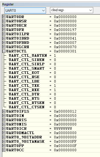
Any idea what could cause this behavior? There must be something different, but I have checked stuff all day long and have come up with nothing.


Thanks,

Dave

  • Two things to check. Your terminal emulator's settings and the actual bit sequence sent. Best guess is a baud rate mismatch, a simple scope check is really a necessary sanity check.

    Robert
  • Hi, Robert,

    I had dismissed the idea of a baud rate problem since my code is setting the same baud rate as the sample code (which works fine), and even checked that the UART's control registers (including the baud rate dividers) are identical to the sample code.


    However, your post got me thinking about this again, and if the baud rate were off by a factor of 2 that would certainly explain what I am seeing. What might be happening is that the system clock is not the same between the 2 systems. They are supposed to be both running at 120 MHz, but the example code is using a TivaWare call to set the clock, and my code is using an RTOS function to do it. It may be that there is a bug that is causing the clock to be off, which would affect the baud rate.

    I will look into this when I get back into the office on Monday, and report my findings. Thanks for the post!

    Regards,

    Dave

  • Dave Hohl said:

    For example, when I try to send "Testing" I get the following bytes received by the terminal emulator:

    28 FF C9 FF E7 FF E8 FF D1 FF DE FF CF FF

    Another odd thing is that if I run at full speed I do not see all the characters sent out. Instead, the terminal emulator receives

    28 19 21 FF 

    Of course monitoring of the actual data being output makes sense.    That said - is there not an (unnoted) inconsistency w/in the post's listing, quoted above?   In case #1, 7 chars are sent - 14 received.   In case #2, (it's assumed) those same 7 are sent - and now just 4 received.   (post is silent as to the conditions under case #1!)

    Often we note that if a baud-rate conflict appears - and if constant (i.e. repeated data) is sent - that data (although received in error) will remain consistent.   Your "Testing" test transmission does not provide a data duplication - yet we note that "T & t" are present.   Hex codes are 0x54 & 0x74 - you've recorded 0x28 & 0xE8. (at the receiver) 

    I too bet that the baud rate is mismatched - and that the "Stop Bit" is responsible for the (illegal) 0xFF.  

    Further - there is NO logical consistency (which I can note) between 0x54 (T) being received as 0x28 - and then 0x74 (t) arriving as 0xE8.

    Bits:  7654   3210

    ......... 0101   0100   0x54   Sent "T"

    ......... 0010   1000   0x28   Received

    Note the received (almost) is shifted right by 1 bit pos'n.  (yet one bit is lost! [bit 2])

    And here's the "t" analysis:

    ........ 0111   0100   0x74   Sent "t"

    ........ 1110  1000    0xE8  Received

    We now note the data has shifted left (1 bit pos'n) or has shifted by an even greater amount, right.  (although that appears unlikely)   And this time - we got it all!

    I had high hopes that "back of the envelope" poking would yield insight - Fails!   (or demands better mind than mine to detect...)   Ratz!

  • Glad I could spark a thought Dave.

    It did seem a good place to divide the problem in two.

    Robert

    Dividing the problem being one of the two essentials to debugging.
  • Robert Adsett72 said:
    Dividing the problem being one of the two essentials to debugging.

    Just "two?"   Hazard the guess that unless these essentials are rendered very "broad" - two proves too few.  

    Conditions prior to and during any "debug" are likely to impact - thus may register as "essential" as well...

  • Yep, I think two. The other is forming and testing hypotheses of how the system behaves.

    That makes it sound easier than it is but I believe it's valid. You will note the second principle dovetails nicely with TDD.

    Robert
  • I believe we are impaled upon (past presidential) issue: "What "is" is?" (replace "is" w/debugging)
  • I did a little testing of things, and as I had surmised on Saturday after reading Robert's post, the issue is not in the configuration of the baud rate per se, but rather that for some reason the system clock frequency in my custom code is different from that in the example code. I added a call to MAP_SysCtlClockFreqSet() to set the freq to 120 MHz, and now things are working fine.

    Next on the list is to figure out why my code is not setting the clock to the frequency I thought it was!

    Thanks again for steering me in the right direction regarding this problem. It's another example of how the assumptions we make (in this case, my assuming that since the UART was configured the same way in both my code and the example code, the baud rate must be the same) can interfere with the debugging process!

    Regards,

    Dave

  • Hello Dave

    Which brings up the question, what was the system clock frequency in the custom code being configured as?

    Regards
    Amit
  • Hi, Amit,

    It was supposed to be 120 MHz as well. That's why I need to investigate to see what is going wrong. I will let you know what I find out.

    Regards,

    Dave
  • Hello Dave

    If the device system clock is not being programmed or configured explicitly, then there are 2 likely cases.

    1. The System Clock reverts to PIOSC of 16MHz, if the after code load there is a System Reset (not just a core reset).
    2. If there is a core reset then the boot loader clock may be getting used which would be 60MHz if the main oscillator is getting detected.

    Regards
    Amit
  • Hi, Amit,

    The RTOS init code configures the system clock. I thought it was setting it to 120 MHz, and the frequency of my blinking LED made me believe that was the case. But obviously something is not as it appears.

    Regards,

    Dave
  • Hello Dave,

    I would suggest adding a Timer in PWM Mode with a CCP Output such that the output pin toggles at 1/1000 of the system clock. Monitoring the same in the custom code will tell us what the system frequency is.

    You are right though, that if the RTOS is being used it must be configuring it to 120MHz (with the assumption of a 25MHz crystal as the clock source, unless the actual crystal is some other value)

    Regards
    Amit
  • I believe I have discovered 2 bugs in the RTOS' clock initialization code. The first one is pretty major. The PSYDIV field in the RSCLKCFG register is being set to 4 instead of 3. They divided the 480 MHZ VCO by the 120 MHz desired system clock, but neglected to subtract out 1 to get the proper PSYDIV value.

    The second bug might or might not be important. The value being written to the MEMTIM0 register is 0x01B6.01B6 instead of the proper 0x0195.0195 value. They appear to be using the wrong table to set the values. They are using:


    * +-----------------------+--------------------------+-------------+-----------+---------+ * | CPU Freq. Range(F) in | Time Period Range (t) in | FBCHT/EBCHT | FBCE/EBCE | FWS/EWS | * | MHz | ns | | | | * +-----------------------+--------------------------+-------------+-----------+---------+ * | 16 | 62.5 | 0 | 1 | 0 | * | 16 < f <= 30 | 62.5 > f >= 33.3 | 1 | 1 | 1 | * | 30 < f <= 50 | 33.3 > f >= 20 | 2 | 1 | 2 | * | 50 < f <= 60 | 20 > f >= 16.67 | 3 | 0 | 3 | * | 60 < f <= 80 | 16.67 > f >= 12.5 | 4 | 0 | 4 | * | 80 < f <= 100 | 12.5 > f >= 10 | 5 | 0 | 5 | * | 100 < f <= 120 | 10 > f >= 8.33 | 6 | 0 | 6 | * +-----------------------+--------------------------+-------------+-----------+---------+

    The datasheet I have for the TM4C129EKCPDT shows different entries in the table:

    The TivaWare MAP_SysCtlClockFreqSet() sets up the MEMTIM0 register properly according to the chart in the data sheet. The EEPROM seems to work okay using the incorrect register values, but that might just be the result of luck.


    I will be contacting Micrium regarding these problems.

    Regards,

    Dave

  • Hello Dave,

    Good find. Is the RTOS uCOS-III from Micrium (as it surprises me since this was a basic system initialization that should have been taken care in the API implementation within the OS)?

    Regards
    Amit
  • Hi, Amit,


    Yes, the RTOS is uC-OS-III from Micrium. I, too, was surprised by this bug. Micrium has a very high quality product, so it is hard to explain how such a basic function such as setting the system clock freq could be wrong.

    The code is not in the core OS, but rather in their board support package for the DK-TM4C129X dev kit.

    Micrium has confirmed the bug, and plans to have a fix available on their web site by the end of the week.

    Regards,

    Dave

  • Dave Hohl said:
    plans to have a fix available on their web site by the end of the week.

    If so notable an error could pass unchecked (but for Dave) what else may lurk?

    This may signal the need for a deeper review - any "rush" to correct may not prove in users' best interest...

  • Hello Dave,

    Thanks for letting us know on the follow up. This is indeed very surprising and it may be possible that other drivers need to be checked as well by Micrium.

    Regards
    Amit
  • We hear an echo...
  • I looked more closely at the board support package code, and the only things they set up besides the system clock are the IVT and a timer used for internal timekeeping. So there is not much else that could have problems.

    Regards,

    Dave