This thread has been locked.

If you have a related question, please click the "Ask a related question" button in the top right corner. The newly created question will be automatically linked to this question.

Problem using QEI module on TM4C123GH6PM

Other Parts Discussed in Thread: TM4C123GH6PM

I'm new to Tiva and has just finish the basic examples in Tiva Lauchpad Workshop. My very first project is to close-looped control the DC motor's velocity so I'm trying to work with the QEI module for velocity feedback. The code shown below is my build base on the posts about QEI on this forum and the Tiva Peripheral Library document.

This code was built and debugged without error. The problem is when I try to place a breakpoint on the line which calculate the qei_velocity variable, then configure the breakpoint to update the value of velocity on the expression window without halting the result is always 0. I don't know if there's anything not right in the code itself, the way I place the breakpoint or the hardware (which I believe is right).

Here's the code:

#include <stdbool.h>
#include <stdint.h>
#include "inc/tm4c123gh6pm.h"
#include "inc/hw_memmap.h"
#include "driverlib/gpio.h"
#include "driverlib/pin_map.h"
#include "driverlib/sysctl.h"
#include "driverlib/interrupt.h"
#include "driverlib/qei.h"

int qei_position;
int qei_velocity;

extern void QEI1IntHandler(void)
{
unsigned long status;
status = QEIIntStatus(QEI1_BASE, false);
if ((status & QEI_INTTIMER) == QEI_INTTIMER)
{
QEIIntClear(QEI1_BASE, QEI_INTTIMER);
qei_position = QEIPositionGet(QEI1_BASE);
qei_velocity = QEIVelocityGet(QEI1_BASE) * QEIDirectionGet(QEI1_BASE);
}
}

void main(void)
{
SysCtlClockSet(SYSCTL_SYSDIV_5 | SYSCTL_USE_PLL | SYSCTL_OSC_MAIN | SYSCTL_XTAL_16MHZ);


SysCtlPeripheralEnable(SYSCTL_PERIPH_QEI1);
SysCtlPeripheralEnable(SYSCTL_PERIPH_GPIOC);
QEIConfigure(QEI1_BASE, QEI_CONFIG_CAPTURE_A_B | QEI_CONFIG_NO_RESET
| QEI_CONFIG_QUADRATURE | QEI_CONFIG_SWAP, 0xFFFFFFFF);
GPIOPinTypeQEI(GPIO_PORTC_BASE, GPIO_PIN_5 | GPIO_PIN_6);


GPIOPinConfigure(GPIO_PC5_PHA1);
GPIOPinConfigure(GPIO_PC6_PHB1);
QEIVelocityConfigure(QEI1_BASE, QEI_VELDIV_2, SysCtlClockGet()/50); //20 ms period
QEIVelocityEnable(QEI1_BASE);
QEIEnable(QEI1_BASE);

QEIIntEnable(QEI1_BASE, QEI_INTTIMER);
QEIIntRegister(QEI1_BASE, &QEI1IntHandler);
IntEnable(INT_QEI1);
IntMasterEnable();

GPIOPadConfigSet(GPIO_PORTC_BASE, GPIO_PIN_5 | GPIO_PIN_6, GPIO_STRENGTH_8MA_SC, GPIO_PIN_TYPE_STD_WPU);
while(1)
{

}

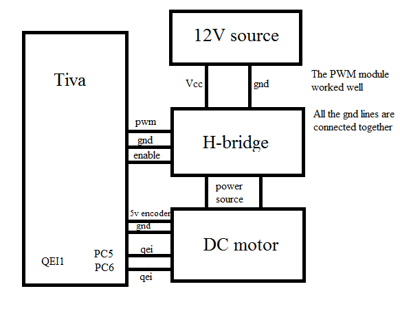
Here's the hardware's setting. Thank you sincerely.
}

  • Hello Le,

    The QEI direction returned is -1 or 1 based on the direction. Which means that the variable needs to have signed value. The first step would be to check if the QEIVelocityGet returns the value before applying the direction to the multiplier.

    BTW, excellent description of issue and block diagram illustrating the system.

    Regards
    Amit
  • Hi Amit,

    We noted the direction variable's impact upon the velocity variable too. Indeed as you state - poster must "decouple" the direction from the raw velocity calc.

    Poster, "Believes the HW is right" - minus any recitation of his test/verify - that's, "No sure thing." Does his motor and/or the Encoder provide proper - TM4C compatible - signal levels? Do those signals reach the proper MCU pins? Might other connections also appear upon those pins - able to degrade/spoil those QEI signals?

    Code focus is important - but poster has created a "system" - and it is always wise to "test/verify" the individual (external) system components "before" applying their (unchecked) outputs to the MCU. "Belief" (minus the rigor of real test/verify) often proves unwarranted...

  • Problem's not solved. I don't think the signed or unsigned thing led to the result of 0. I think the problem should lie on the interrupt routine or the breakpoint and still working on that.
    Appreciate your attention.
  • Thanks for your advice.
    1) The MCU and motor brand are ones I saw in a robot competition and I actually have a chance to bring it home for analyzing the hardware and how they connect to the MCU.
    2) I do test components individually, in this case the PWM module works perfectly and the motor has a led to indicate the encoder's working status.
    Due to the lack of experience I decide to work on just one problem at a time, and I have the feeling that's something is not right about the interrupt routine and the breakpoint config so they're my priorities.
  • @Le,

    It's your project - yet the glow of a single Led does not provide (real) comfort.

    Even w/experience - "KISS" (some mention that here) dictates that the project be broken into small (manageable) parts - with each tested individually.

    There's danger in your connecting that "robot competition encoder output" directly to your MCU!   Can that single, encoder Led (fully/properly) confirm that encoder's signal levels are w/in MCU's spec?   (we much doubt that!)

    As past advised - external systems/connections should ALWAYS be "test/verified" prior to attaching to a "vulnerable/expensive/hard to replace" MCU. Skipping that, "external device signal's test/verify" may not prove a shortcut if you've damaged the MCU...

  • @Le,

    Somehow I cannot edit the post above...

    You should be able to drive either or both of the MCU's QEI inputs w/"proper" GPIO outputs w/in your MCU! This method "insures" that signal levels are correct/proper - and that the encoder ground (indeed) ties to MCU ground. (by the elimination of the encoder - for now)

    Choose a Timer pin(s) - force that timer into PWM mode - and start w/~100Hz PWM frequency, 50% duty. That's an essentially "foolproof" means to exercise & test/verify your QEI module (and your QEI code) - and (completely) removes the motor/encoder from your issue.   (I'm unsure if the MCU's QEI module "demands" a true "Quadrature" input - upon both QEI pins - this "faked Quad" can be achieved via this method - but is far more demanding, "messier.")
     
    KISS rules - "kitchen-sink" (all at once) Not so much...

  • Hi,

    Le Thai said:
    The problem is when I try to place a breakpoint on the line which calculate the qei_velocity variable, then configure the breakpoint to update the value of velocity on the expression window without halting the result is always 0.

    I'm not sure I understand 100 % what you're trying to say here. Does the velocity value appear correct when you halt the program flow with the breakpoint? And what do you mean by configuring the breakpoint to update the value on the expression window?

    What I think you need to do is just to have the name of the variable in the expression window (you already have it defined in the global scope, so it should work) and then enable continuous updating from the top of the expression window.

    Also, I'd suggest declaring the variables as volatile - if any sort of optimization is enabled, the compiler might decide to simply ignore the variable because it looks like it's never updated in the main program flow!

    Another suggestion is to add a new variable, "volatile int qei_intcounter = 0;", and in your QEI inthandler, add "qei_intcounter++;". Then add the variable to your expression window and see that it is being updated - if it is not, you have a problem somewhere in your QEI configuration.

    And I add my vote of support for cb1's suggestion of (re-)checking the encoder signals preferably with a scope/logic analyzer. You will want to know that whatever you're going to connect to the microcontroller is what you expect it to be.

  • Hello Veikko,

    A Scope should be more useful to see the signals. A LA configured to monitor signals at some threshold point may just show a 1 and 0. A Scope shall bring in the voltage levels. Also one interesting thing I did in the code is the use of Weak Pull Up of the IP's whcih suggest that there is a Open Drain output from the Sensors and may require inversion of the signals in the QEI module.

    Regards
    Amit
  • Also be ware that weak pull-ups may be insufficient for something like a quadrature encoder. They may require quite strong pull-ups and they may not work with a 3V interface. As Amit says a 'scope is necessary to verify the signal.

    As cb1 says verify one thing at a time. There is a lot to be said for verifying S/W and H/W separately.

    Robert
  • Problem's solved! This morning I happened to walk into a senior who had just completed his thesis and he was welcomed to hear my problem. It turned out that he was once experience that and told me to forget about the breakpoint thing, just built a GUI and see what was actually transfered. So I built a GUI using Visual Studio to receive data of the velocity and position values obtained from the encoder and it worked well. The received numbers are meaningful.

    I will have some time to figure out why the breakpoint watching method didn't work but not now.

    Best regards for Amit Asara, cb1-, Veikko Immonen and Robert Adsett. I would be very appreciated to have your support from now on.
  • Hello Le,

    That is strange. So wouldn't that mean that the variable actually gets updates but for some reason CCS watch window does not show. This in turn would mean that the Refresh was not switched on in the watch window!!!!

    Regards
    Amit
  • So - lesson learned here: (sigh)...count upon an "accidental" meeting - forget about breakpoints - quickly build a GUI which some way/how "captures" past "uncaptureable data" - and all will, "Be well."

    Somehow (at least to moi) this seems not the "best ever" Suggested Answer...  (or staff/I must increase our "walks" and search out those "welcoming our issues...")

  • It's just one kind of solution I found by mere luck, and I saw guys who didn't verify or suggest others' answer get scruntinized for their irresponsibility on this forum so I thought clicking on the button was OK. 

    And sorry for not meeting your expectation to manage a throughout solution. (sigh)

  • As Amit & I have noted - your "newfound" ability to capture & read the (previously) inscrutable "velocity variable" (still) deserves (some) explanation... (to the benefit of many...)