This thread has been locked.
If you have a related question, please click the "Ask a related question" button in the top right corner. The newly created question will be automatically linked to this question.
Hello,
I am making some tests on the evaluation board EK-TM4C1294XL. I am trying to make the board talk to the CC1110 via SPI bus.
I managed to make the Ti-RTOS SPI loopback example works on the evaluation board. The CC1110 is the master and the TM4C is the slave.
In our test we were using the SSI3 peripheral.
The program running on the CC1110 can also communicate with other C1110 via SPI.
So it seems that the problem come from voltage difference between the CC1110 and the evaluation board.
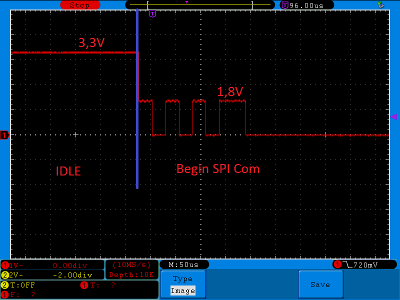
In fact, we found that the PQ2 pin is forcing the MOSI pin to 1,8 V instead of 3,3V which is the power supply of the CC1110 and the evaluation board. That's why the SPI transaction end well (return OK) but return only 0's.
For information, the CC1110 is powered by the CC debugger and the evaluation board is powered by the on-board debugger.
Thank you in advance for your help,
If you need any further informations (code, images), please ask.
Best Regards,
Yannick Riou
Hello,
Thank you for your prompt answer. There is 3,3V even if the PQ2 pin is connected to the CC1110. The problem appears when the SPI communication begins.
As you can see on the picture linked. On idle state (when there is no SPI communication), there is 3,3V on PQ2 pin. When the SPI communication begins, the voltage drops to 1,8V. When it ends, the voltage go back to 3,3V.
Please also find linked the source code that I am using for the Cortex-M4.
Thank you in advance for your help.
Best regards,
Yannick
/* * Copyright (c) 2015, Texas Instruments Incorporated * All rights reserved. * * Redistribution and use in source and binary forms, with or without * modification, are permitted provided that the following conditions * are met: * * * Redistributions of source code must retain the above copyright * notice, this list of conditions and the following disclaimer. * * * Redistributions in binary form must reproduce the above copyright * notice, this list of conditions and the following disclaimer in the * documentation and/or other materials provided with the distribution. * * * Neither the name of Texas Instruments Incorporated nor the names of * its contributors may be used to endorse or promote products derived * from this software without specific prior written permission. * * THIS SOFTWARE IS PROVIDED BY THE COPYRIGHT HOLDERS AND CONTRIBUTORS "AS IS" * AND ANY EXPRESS OR IMPLIED WARRANTIES, INCLUDING, BUT NOT LIMITED TO, * THE IMPLIED WARRANTIES OF MERCHANTABILITY AND FITNESS FOR A PARTICULAR * PURPOSE ARE DISCLAIMED. IN NO EVENT SHALL THE COPYRIGHT OWNER OR * CONTRIBUTORS BE LIABLE FOR ANY DIRECT, INDIRECT, INCIDENTAL, SPECIAL, * EXEMPLARY, OR CONSEQUENTIAL DAMAGES (INCLUDING, BUT NOT LIMITED TO, * PROCUREMENT OF SUBSTITUTE GOODS OR SERVICES; LOSS OF USE, DATA, OR PROFITS; * OR BUSINESS INTERRUPTION) HOWEVER CAUSED AND ON ANY THEORY OF LIABILITY, * WHETHER IN CONTRACT, STRICT LIABILITY, OR TORT (INCLUDING NEGLIGENCE OR * OTHERWISE) ARISING IN ANY WAY OUT OF THE USE OF THIS SOFTWARE, * EVEN IF ADVISED OF THE POSSIBILITY OF SUCH DAMAGE. */ /* * ======== spiloopback.c ======== */ /* XDCtools Header files */ #include <xdc/std.h> #include <xdc/cfg/global.h> #include <xdc/runtime/System.h> /* BIOS Header files */ #include <ti/sysbios/BIOS.h> /* TI-RTOS Header files */ #include <ti/drivers/GPIO.h> #include <ti/drivers/SPI.h> /* Example/Board Header files */ #include "Board.h" #define SPI_MSG_LENGTH 20 /* Allocate buffers in .dma section of memory for concerto devices */ #ifdef MWARE #pragma DATA_SECTION(slaveRxBuffer, ".dma"); #pragma DATA_SECTION(slaveTxBuffer, ".dma"); #endif unsigned char slaveRxBuffer[SPI_MSG_LENGTH]="hello"; unsigned char slaveTxBuffer[SPI_MSG_LENGTH] = "Hello, this is slav"; /* * ======== slaveTaskFxn ======== * Task function for slave task. * * This task runs on a higher priority, since slave * has to be ready for master. Slave SPI sends a * message to master and also receives message from * master. Task for this function is created * statically. See the project's .cfg file. */ Void slaveTaskFxn (UArg arg0, UArg arg1) { SPI_Handle slaveSpi; SPI_Params slaveSpiParams; SPI_Transaction slaveTransaction; bool transferOK; /* Initialize SPI handle with slave mode */ SPI_Params_init(&slaveSpiParams); slaveSpiParams.mode = SPI_SLAVE; // slaveSpiParams. slaveSpi = SPI_open(Board_SPI1, &slaveSpiParams); if (slaveSpi == NULL) { System_abort("Error initializing SPI\n"); System_flush(); } else { System_printf("SPI initialized\n"); System_flush(); } /* Initialize slave SPI transaction structure */ slaveTransaction.count = SPI_MSG_LENGTH; slaveTransaction.txBuf = NULL;//(Ptr)slaveTxBuffer; slaveTransaction.rxBuf = (Ptr)slaveRxBuffer; while(1) { /* Initiate SPI transfer */ transferOK = SPI_transfer(slaveSpi, &slaveTransaction); if(transferOK) { /* Print contents of slave receive buffer */ System_printf("Slave: %d\n", slaveRxBuffer[0]); System_flush(); } else { System_printf("Unsuccessful slave SPI transfer"); System_flush(); } } /* Deinitialize SPI */ SPI_close(slaveSpi); } /* * ======== main ======== */ int main(void) { /* Call board init functions. */ Board_initGeneral(); Board_initGPIO(); Board_initSPI(); /* Turn on user LED */ GPIO_write(Board_LED0, Board_LED_ON); System_printf("Starting the SPI loop-back example\nSystem provider is set to" " SysMin. Halt the target to view any SysMin contents in ROV.\n"); /* SysMin will only print to the console when you call flush or exit */ System_flush(); System_printf("This example requires external wires to be connected to the " "header pins. Please see the Getting Started Guide for " "details.\n"); /* SysMin will only print to the console when you call flush or exit */ System_flush(); /* Start BIOS */ BIOS_start(); return (0); }
Hello Amit,
Amit Ashara said:2. Check the GPIO Port Q configuration of the SSI3 module using the debugger to see if they are in SSI mode
So if I understand well, the PQ2 acts as MOSI pin, so everything is well configured... Moreover I use an example I just modified to only test the slave task, so normally it should work !
Thanks again,
Best Regards,
Yannick
Hello,
the problem is here again even with the resistor desoldered. Can you send to me the bare metal code that you used to make it work ?
Thank you in advance,
Best regards,
Yannick Riou
Finally ! I found that the PQ2 is acting as TX and I was connecting the CC1110 to the SSI3 according to the getting started documentation shipped with the evaluation board. I switched PQ2 and PQ3 and now it's working well ! But I don't manage to understand why I need to switch the two pin's.
Best Regards,
Yannick