This thread has been locked.

If you have a related question, please click the "Ask a related question" button in the top right corner. The newly created question will be automatically linked to this question.

LCD Controller TIVAC129

Hello.

I've done a simple project with TIVAC129, I mean a main() with a while(1).

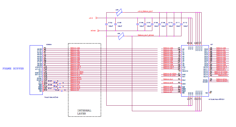
The program init the SDRAM and LCD controller in order to display a simple pattern on LCD Screen (black or red backgroud).

The main issue is that after all init the LCD screen is doing strange behaviour: it continuosly roll over red, blue, green grey,... but I never init this values into SDRAM.


Which is the explanation of this behaviour?


Regards,

Marco


  • Marco Crivellari said:
    What is the explanation of this behaviour?

    Might three possibilities be most likely?

    • Display has a "mind" of its own
    • Your code is improper
    • Your connections to the display are improper

    Far more detail is required to assist...

  • Hello Marco

    I have worked with both Raster and Smart Panels with SDRAM on the TM4C129X devices and have seen no issue. Can you publish you code, schematics (as cb1 already said) so that others can check if there is an issue.

    Regards
    Amit
  • The fact is that I have an application that run on TIRTOS and works fine with the same driver.

    The only difference is that this application is a simple main and I have no early configuration for port.

    Below my code:

    -----------------------------
    /*
    * \file lcd_hal.c
    */
    #include "HAL/lcd/lcd_hal.h"
    #include "driverlib/epi.h"
    #include "driverlib/lcd.h"


    // **********************************************************************************************
    //
    // Defines and structs
    //
    // **********************************************************************************************
    typedef struct LCDControlStruct
    {
    int pendingBuffer;
    int activeBuffer;
    int currentBuffer;
    int refresh;
    int enable;
    unsigned long counter;
    int srcIndex;
    int destIndex;
    Bool pendingCopy;
    Bool newFrame;

    } LCDControl;

    /**
    * \brief Timing structure for LCD parameters.
    */
    static tLCDRasterTiming sTimings;

    void LCDIntHandler(void)
    {
    uint32_t ui32Status;

    //
    // Get the current interrupt status and clear any active interrupts.
    //
    ui32Status = LCDIntStatus(LCD0_BASE, false);


    if( (ui32Status & LCD_INT_UNDERFLOW ) > 0 )
    {
    LCDRasterEnable(LCD0_BASE);
    }

    // Clear interrupt
    LCDIntClear(LCD0_BASE, ui32Status);
    }

    void LCDCopyBufferConf(int LayerIndex, int IndexSrc, int IndexDst)
    {
    unsigned long BufferSize, AddrSrc, AddrDst, value;


    //
    // Calculate the size of one frame buffer
    //
    BufferSize = LCD_FRAME_BUFFER_SIZE;

    //
    // Calculate source- and destination address
    //
    AddrSrc = LCD_FRAME_BUFFER_PTR + BufferSize * IndexSrc;
    AddrDst = LCD_FRAME_BUFFER_PTR + BufferSize * IndexDst;

    while( BufferSize > 0 )
    {
    value = *((uint8_t*)AddrSrc );
    EPIWorkaroundByteWrite( (uint8_t*)AddrDst, value );
    AddrDst++;
    AddrSrc++;
    BufferSize--;
    }
    }


    //*****************************************************************************
    //
    //! Initializes the display driver.
    //!
    //! \param ui32SysClock is the frequency of the system clock.
    //!
    //! This function initializes the LCD controller and the SSD2119 display
    //! controller on the panel, preparing it to display data.
    //!
    //! \return None.
    //
    //*****************************************************************************
    #define LCD_DMA_PRIORITY_7 0x00070000
    void LCDHal_LowLevel_Init(unsigned long int ui32SysClock)
    {
    uint32_t ui32PixelClock;
    uint32_t *ui32FrameBuffer;
    uint32_t ui32Count = 0;


    // Get Pixel Clock
    // Nota bene: utilizzando come frame buffer 0x60000000 abbiamo un pixel-clock di 12MHz (divisore 10 su 120MHz)
    // altrimenti il refresh dello schermo mostra delle righe rosse.
    //
    ui32PixelClock = ui32SysClock / 4;

    LCDModeSet(LCD0_BASE, LCD_MODE_RASTER | LCD_MODE_AUTO_UFLOW_RESTART, ui32PixelClock, ui32SysClock);

    LCDRasterConfigSet(LCD0_BASE, RASTER_FMT_ACTIVE_24BPP_UNPACKED | RASTER_LOAD_DATA_ONLY, 0);

    sTimings.ui32Flags = RASTER_TIMING_SYNCS_ON_RISING_PIXCLK | RASTER_TIMING_ACTIVE_HIGH_OE |
    RASTER_TIMING_ACTIVE_HIGH_PIXCLK | RASTER_TIMING_ACTIVE_HIGH_HSYNC | RASTER_TIMING_ACTIVE_HIGH_VSYNC;

    sTimings.ui16PanelWidth = XSIZE_PHYS;
    sTimings.ui16PanelHeight = YSIZE_PHYS;

    sTimings.ui16HFrontPorch = 20;
    sTimings.ui16HBackPorch = 216;
    sTimings.ui16HSyncWidth = 1;

    sTimings.ui8VFrontPorch = 5;
    sTimings.ui8VBackPorch = 35;
    sTimings.ui8VSyncWidth = 1;

    sTimings.ui8ACBiasLineCount = 0;
    LCDRasterTimingSet(LCD0_BASE, &sTimings);

    //
    // See LCD_SetVRAMAddrEx.
    // The function requires a display driver which is able to manage dynamically changes of the
    // video RAM address. If the display driver does not support this feature the function fails.
    //
    LCDDMAConfigSet( LCD0_BASE, LCD_DMA_PRIORITY_7 | LCD_DMA_BURST_16 | LCD_DMA_FIFORDY_512_WORDS | LCD_DMA_BYTE_ORDER_0123 );
    //LCDDMAConfigSet( LCD0_BASE, LCD_DMA_BURST_16 | LCD_DMA_FIFORDY_64_WORDS );

    LCDRasterFrameBufferSet( LCD0_BASE, 0, (uint32_t*)LCD_FRAME_BUFFER_PTR, LCD_FRAME_BUFFER_SIZE );

    //LCDRasterPaletteSet(LCD0_BASE, LCD_PALETTE_TYPE_DIRECT, (uint32_t *)(LCD_FRAME_BUFFER_PTR), 0, 0, 0);

    #if 1
    //
    // Clear the contents of the display buffer is done by Gui_Init() => force all zero(s)
    //
    ui32FrameBuffer = (uint32_t *)(LCD_FRAME_BUFFER_PTR);
    for(ui32Count = 0; ui32Count < (XSIZE_PHYS * YSIZE_PHYS * NUM_BUFFERS); ui32Count++)
    {
    #if SDRAM_AT_0x10
    EPIWorkaroundWordWrite( ui32FrameBuffer, 0x0000000 );
    ui32FrameBuffer++;
    #else
    *ui32FrameBuffer = 0x0000000;
    ui32FrameBuffer++;
    #endif
    }
    #endif

    //LCDIntEnable( LCD0_BASE, LCD_INT_RASTER_FRAME_DONE | LCD_INT_EOF0 | LCD_INT_EOF1 | LCD_INT_UNDERFLOW);
    //LCDIntEnable( LCD0_BASE, (LCD_INT_DMA_DONE | LCD_INT_SYNC_LOST | LCD_INT_UNDERFLOW | LCD_INT_EOF0) );
    //IntEnable( INT_LCD0 );

    LCDRasterEnable( LCD0_BASE );
    }
  • Hello Marco

    I do not see if the IOs for the LCD controller or for that matter for EPI is being configured.

    Regards
    Amit
  • //*****************************************************************************
    // Copyright (c) 2014 Texas Instruments Incorporated. All rights reserved.
    // Software License Agreement
    //
    // Redistribution and use in source and binary forms, with or without
    // modification, are permitted provided that the following conditions
    // are met:
    //
    // Redistributions of source code must retain the above copyright
    // notice, this list of conditions and the following disclaimer.
    //
    // Redistributions in binary form must reproduce the above copyright
    // notice, this list of conditions and the following disclaimer in the
    // documentation and/or other materials provided with the
    // distribution.
    //
    // Neither the name of Texas Instruments Incorporated nor the names of
    // its contributors may be used to endorse or promote products derived
    // from this software without specific prior written permission.
    //
    // THIS SOFTWARE IS PROVIDED BY THE COPYRIGHT HOLDERS AND CONTRIBUTORS
    // "AS IS" AND ANY EXPRESS OR IMPLIED WARRANTIES, INCLUDING, BUT NOT
    // LIMITED TO, THE IMPLIED WARRANTIES OF MERCHANTABILITY AND FITNESS FOR
    // A PARTICULAR PURPOSE ARE DISCLAIMED. IN NO EVENT SHALL THE COPYRIGHT
    // OWNER OR CONTRIBUTORS BE LIABLE FOR ANY DIRECT, INDIRECT, INCIDENTAL,
    // SPECIAL, EXEMPLARY, OR CONSEQUENTIAL DAMAGES (INCLUDING, BUT NOT
    // LIMITED TO, PROCUREMENT OF SUBSTITUTE GOODS OR SERVICES; LOSS OF USE,
    // DATA, OR PROFITS; OR BUSINESS INTERRUPTION) HOWEVER CAUSED AND ON ANY
    // THEORY OF LIABILITY, WHETHER IN CONTRACT, STRICT LIABILITY, OR TORT
    // (INCLUDING NEGLIGENCE OR OTHERWISE) ARISING IN ANY WAY OUT OF THE USE
    // OF THIS SOFTWARE, EVEN IF ADVISED OF THE POSSIBILITY OF SUCH DAMAGE.
    //
    // This file was automatically generated by the Tiva C Series PinMux Utility
    // Version: 1.0.4
    //
    //*****************************************************************************

    #include <stdint.h>
    #include <stdbool.h>
    #include "port.h"
    #include "inc/hw_types.h"
    #include "inc/hw_memmap.h"
    #include "inc/hw_gpio.h"
    #include "driverlib/sysctl.h"
    #include "driverlib/pin_map.h"
    #include "driverlib/gpio.h"

    //*****************************************************************************
    void
    PortFunctionInit(void)
    {
    //
    // Enable Peripheral Clocks
    //
    SysCtlPeripheralEnable(SYSCTL_PERIPH_ADC0);
    SysCtlPeripheralEnable(SYSCTL_PERIPH_CAN0);
    SysCtlPeripheralEnable(SYSCTL_PERIPH_EPHY0);
    SysCtlPeripheralEnable(SYSCTL_PERIPH_EPI0);
    SysCtlPeripheralEnable(SYSCTL_PERIPH_I2C2);
    SysCtlPeripheralEnable(SYSCTL_PERIPH_I2C3);
    SysCtlPeripheralEnable(SYSCTL_PERIPH_LCD0);
    SysCtlPeripheralEnable(SYSCTL_PERIPH_SSI1);
    SysCtlPeripheralEnable(SYSCTL_PERIPH_SSI2);
    SysCtlPeripheralEnable(SYSCTL_PERIPH_SSI3);
    //SysCtlPeripheralEnable(SYSCTL_PERIPH_TIMER0);
    //SysCtlPeripheralEnable(SYSCTL_PERIPH_TIMER1);
    SysCtlPeripheralEnable(SYSCTL_PERIPH_UART3);
    SysCtlPeripheralEnable(SYSCTL_PERIPH_UART4);
    SysCtlPeripheralEnable(SYSCTL_PERIPH_UART5);
    SysCtlPeripheralEnable(SYSCTL_PERIPH_UART6);
    SysCtlPeripheralEnable(SYSCTL_PERIPH_USB0);
    SysCtlPeripheralEnable(SYSCTL_PERIPH_GPIOA);
    SysCtlPeripheralEnable(SYSCTL_PERIPH_GPIOB);
    SysCtlPeripheralEnable(SYSCTL_PERIPH_GPIOC);
    SysCtlPeripheralEnable(SYSCTL_PERIPH_GPIOD);
    SysCtlPeripheralEnable(SYSCTL_PERIPH_GPIOE);
    SysCtlPeripheralEnable(SYSCTL_PERIPH_GPIOF);
    SysCtlPeripheralEnable(SYSCTL_PERIPH_GPIOG);
    SysCtlPeripheralEnable(SYSCTL_PERIPH_GPIOH);
    SysCtlPeripheralEnable(SYSCTL_PERIPH_GPIOJ);
    SysCtlPeripheralEnable(SYSCTL_PERIPH_GPIOK);
    SysCtlPeripheralEnable(SYSCTL_PERIPH_GPIOL);
    SysCtlPeripheralEnable(SYSCTL_PERIPH_GPIOM);
    SysCtlPeripheralEnable(SYSCTL_PERIPH_GPION);
    SysCtlPeripheralEnable(SYSCTL_PERIPH_GPIOP);
    SysCtlPeripheralEnable(SYSCTL_PERIPH_GPIOQ);
    SysCtlPeripheralEnable(SYSCTL_PERIPH_GPIOR);
    SysCtlPeripheralEnable(SYSCTL_PERIPH_GPIOS);
    SysCtlPeripheralEnable(SYSCTL_PERIPH_GPIOT);

    //
    // Enable pin PE0 for ADC AIN3
    //
    GPIOPinTypeADC(GPIO_PORTE_BASE, GPIO_PIN_0);

    //
    // Enable pin PE1 for ADC AIN2
    //
    GPIOPinTypeADC(GPIO_PORTE_BASE, GPIO_PIN_1);

    //
    // Enable pin PA1 for CAN0 CAN0TX
    //
    GPIOPinConfigure(GPIO_PA1_CAN0TX);
    GPIOPinTypeCAN(GPIO_PORTA_BASE, GPIO_PIN_1);

    //
    // Enable pin PA0 for CAN0 CAN0RX
    //
    GPIOPinConfigure(GPIO_PA0_CAN0RX);
    GPIOPinTypeCAN(GPIO_PORTA_BASE, GPIO_PIN_0);

    //
    // Enable pin PQ4 for DIVSCLK0 DIVSCLK
    //
    GPIOPinConfigure(GPIO_PQ4_DIVSCLK);
    GPIOPinTypeGPIOOutput(GPIO_PORTQ_BASE, GPIO_PIN_4);

    //
    // Enable pin PK6 for EPHY0 EN0LED1
    //
    GPIOPinConfigure(GPIO_PK6_EN0LED1);
    GPIOPinTypeEthernetLED(GPIO_PORTK_BASE, GPIO_PIN_6);

    //
    // Enable pin PK4 for EPHY0 EN0LED0
    //
    GPIOPinConfigure(GPIO_PK4_EN0LED0);
    GPIOPinTypeEthernetLED(GPIO_PORTK_BASE, GPIO_PIN_4);

    //
    // Enable pin PF1 for EPHY0 EN0LED2
    //
    GPIOPinConfigure(GPIO_PF1_EN0LED2);
    GPIOPinTypeEthernetLED(GPIO_PORTF_BASE, GPIO_PIN_1);

    //
    // Enable pin PM3 for EPI0 EPI0S12
    //
    GPIOPinConfigure(GPIO_PM3_EPI0S12);
    GPIOPinTypeEPI(GPIO_PORTM_BASE, GPIO_PIN_3);

    //
    // Enable pin PH1 for EPI0 EPI0S1
    //
    GPIOPinConfigure(GPIO_PH1_EPI0S1);
    GPIOPinTypeEPI(GPIO_PORTH_BASE, GPIO_PIN_1);

    //
    // Enable pin PC4 for EPI0 EPI0S7
    //
    GPIOPinConfigure(GPIO_PC4_EPI0S7);
    GPIOPinTypeEPI(GPIO_PORTC_BASE, GPIO_PIN_4);

    //
    // Enable pin PB3 for EPI0 EPI0S28
    //
    GPIOPinConfigure(GPIO_PB3_EPI0S28);
    GPIOPinTypeEPI(GPIO_PORTB_BASE, GPIO_PIN_3);

    //
    // Enable pin PA7 for EPI0 EPI0S9
    //
    GPIOPinConfigure(GPIO_PA7_EPI0S9);
    GPIOPinTypeEPI(GPIO_PORTA_BASE, GPIO_PIN_7);

    //
    // Enable pin PH0 for EPI0 EPI0S0
    //
    GPIOPinConfigure(GPIO_PH0_EPI0S0);
    GPIOPinTypeEPI(GPIO_PORTH_BASE, GPIO_PIN_0);

    //
    // Enable pin PG1 for EPI0 EPI0S10
    //
    GPIOPinConfigure(GPIO_PG1_EPI0S10);
    GPIOPinTypeEPI(GPIO_PORTG_BASE, GPIO_PIN_1);

    //
    // Enable pin PH2 for EPI0 EPI0S2
    //
    GPIOPinConfigure(GPIO_PH2_EPI0S2);
    GPIOPinTypeEPI(GPIO_PORTH_BASE, GPIO_PIN_2);

    //
    // Enable pin PP3 for EPI0 EPI0S30
    //
    GPIOPinConfigure(GPIO_PP3_EPI0S30);
    GPIOPinTypeEPI(GPIO_PORTP_BASE, GPIO_PIN_3);

    //
    // Enable pin PC6 for EPI0 EPI0S5
    //
    GPIOPinConfigure(GPIO_PC6_EPI0S5);
    GPIOPinTypeEPI(GPIO_PORTC_BASE, GPIO_PIN_6);

    //
    // Enable pin PC7 for EPI0 EPI0S4
    //
    GPIOPinConfigure(GPIO_PC7_EPI0S4);
    GPIOPinTypeEPI(GPIO_PORTC_BASE, GPIO_PIN_7);

    //
    // Enable pin PG0 for EPI0 EPI0S11
    //
    GPIOPinConfigure(GPIO_PG0_EPI0S11);
    GPIOPinTypeEPI(GPIO_PORTG_BASE, GPIO_PIN_0);

    //
    // Enable pin PM0 for EPI0 EPI0S15
    //
    GPIOPinConfigure(GPIO_PM0_EPI0S15);
    GPIOPinTypeEPI(GPIO_PORTM_BASE, GPIO_PIN_0);

    //
    // Enable pin PC5 for EPI0 EPI0S6
    //
    GPIOPinConfigure(GPIO_PC5_EPI0S6);
    GPIOPinTypeEPI(GPIO_PORTC_BASE, GPIO_PIN_5);

    //
    // Enable pin PL3 for EPI0 EPI0S19
    //
    GPIOPinConfigure(GPIO_PL3_EPI0S19);
    GPIOPinTypeEPI(GPIO_PORTL_BASE, GPIO_PIN_3);

    //
    // Enable pin PA6 for EPI0 EPI0S8
    //
    GPIOPinConfigure(GPIO_PA6_EPI0S8);
    GPIOPinTypeEPI(GPIO_PORTA_BASE, GPIO_PIN_6);

    //
    // Enable pin PM2 for EPI0 EPI0S13
    //
    GPIOPinConfigure(GPIO_PM2_EPI0S13);
    GPIOPinTypeEPI(GPIO_PORTM_BASE, GPIO_PIN_2);

    //
    // Enable pin PK5 for EPI0 EPI0S31
    //
    GPIOPinConfigure(GPIO_PK5_EPI0S31);
    GPIOPinTypeEPI(GPIO_PORTK_BASE, GPIO_PIN_5);

    //
    // Enable pin PH3 for EPI0 EPI0S3
    //
    GPIOPinConfigure(GPIO_PH3_EPI0S3);
    GPIOPinTypeEPI(GPIO_PORTH_BASE, GPIO_PIN_3);

    //
    // Enable pin PL0 for EPI0 EPI0S16
    //
    GPIOPinConfigure(GPIO_PL0_EPI0S16);
    GPIOPinTypeEPI(GPIO_PORTL_BASE, GPIO_PIN_0);

    //
    // Enable pin PL2 for EPI0 EPI0S18
    //
    GPIOPinConfigure(GPIO_PL2_EPI0S18);
    GPIOPinTypeEPI(GPIO_PORTL_BASE, GPIO_PIN_2);

    //
    // Enable pin PL1 for EPI0 EPI0S17
    //
    GPIOPinConfigure(GPIO_PL1_EPI0S17);
    GPIOPinTypeEPI(GPIO_PORTL_BASE, GPIO_PIN_1);

    //
    // Enable pin PM1 for EPI0 EPI0S14
    //
    GPIOPinConfigure(GPIO_PM1_EPI0S14);
    GPIOPinTypeEPI(GPIO_PORTM_BASE, GPIO_PIN_1);

    //
    // Enable pin PP2 for EPI0 EPI0S29
    //
    GPIOPinConfigure(GPIO_PP2_EPI0S29);
    GPIOPinTypeEPI(GPIO_PORTP_BASE, GPIO_PIN_2);

    //
    // Enable pin PB4 for GPIOOutput
    //
    GPIOPinTypeGPIOOutput(GPIO_PORTB_BASE, GPIO_PIN_4);

    //
    // Enable pin PD5 for GPIOOutput
    //
    GPIOPinTypeGPIOOutput(GPIO_PORTD_BASE, GPIO_PIN_5);

    //
    // Enable pin PD2 for GPIOOutput
    //
    GPIOPinTypeGPIOOutput(GPIO_PORTD_BASE, GPIO_PIN_2);

    //
    // Enable pin PD4 for GPIOOutput
    //
    GPIOPinTypeGPIOOutput(GPIO_PORTD_BASE, GPIO_PIN_4);

    //
    // Enable pin PE2 for GPIOOutput
    //
    GPIOPinTypeGPIOOutput(GPIO_PORTE_BASE, GPIO_PIN_2);

    //
    // Enable pin PE6 for GPIOOutput
    //
    GPIOPinTypeGPIOOutput(GPIO_PORTE_BASE, GPIO_PIN_6);

    //
    // Enable pin PE3 for GPIOOutput
    //
    GPIOPinTypeGPIOOutput(GPIO_PORTE_BASE, GPIO_PIN_3);

    //
    // Enable pin PE7 for GPIOOutput
    //

    //
    //First open the lock and select the bits we want to modify in the GPIO commit register.
    //
    HWREG(GPIO_PORTE_BASE + GPIO_O_LOCK) = GPIO_LOCK_KEY;
    HWREG(GPIO_PORTE_BASE + GPIO_O_CR) = 0x80;

    //
    //Now modify the configuration of the pins that we unlocked.
    //
    GPIOPinTypeGPIOOutput(GPIO_PORTE_BASE, GPIO_PIN_7);

    //
    // Enable pin PF4 for GPIOOutput
    //
    GPIOPinTypeGPIOOutput(GPIO_PORTF_BASE, GPIO_PIN_4);

    //
    // Enable pin PF3 for GPIOOutput
    //
    GPIOPinTypeGPIOOutput(GPIO_PORTF_BASE, GPIO_PIN_3);

    //
    // Enable pin PF0 for GPIOOutput
    //
    GPIOPinTypeGPIOOutput(GPIO_PORTF_BASE, GPIO_PIN_0);

    //
    // Enable pin PF5 for GPIOOutput
    //
    GPIOPinTypeGPIOOutput(GPIO_PORTF_BASE, GPIO_PIN_5);

    //
    // Enable pin PF2 for GPIOOutput
    //
    GPIOPinTypeGPIOOutput(GPIO_PORTF_BASE, GPIO_PIN_2);

    //
    // Enable pin PG2 for GPIOOutput
    //
    GPIOPinTypeGPIOOutput(GPIO_PORTG_BASE, GPIO_PIN_2);

    //
    // Enable pin PG3 for GPIOOutput
    //
    GPIOPinTypeGPIOOutput(GPIO_PORTG_BASE, GPIO_PIN_3);

    //
    // Enable pin PH5 for GPIOOutput
    //
    GPIOPinTypeGPIOOutput(GPIO_PORTH_BASE, GPIO_PIN_5);

    //
    // Enable pin PJ7 for GPIOOutput
    //
    GPIOPinTypeGPIOOutput(GPIO_PORTJ_BASE, GPIO_PIN_7);

    //
    // Enable pin PK7 for GPIOOutput
    //
    GPIOPinTypeGPIOOutput(GPIO_PORTK_BASE, GPIO_PIN_7);

    //
    // Enable pin PK2 for GPIOOutput
    //
    GPIOPinTypeGPIOOutput(GPIO_PORTK_BASE, GPIO_PIN_2);

    //
    // Enable pin PM4 for GPIOOutput
    //
    GPIOPinTypeGPIOOutput(GPIO_PORTM_BASE, GPIO_PIN_4);

    //
    // Enable pin PM7 for GPIOOutput
    //
    GPIOPinTypeGPIOOutput(GPIO_PORTM_BASE, GPIO_PIN_7);

    //
    // Enable pin PM6 for GPIOInput
    //
    GPIOPinTypeGPIOInput(GPIO_PORTM_BASE, GPIO_PIN_6);

    //
    // Enable pin PM5 for GPIOInput
    //
    GPIOPinTypeGPIOInput(GPIO_PORTM_BASE, GPIO_PIN_5);

    //
    // Enable pin PP7 for GPIOInput
    //
    GPIOPinTypeGPIOInput(GPIO_PORTP_BASE, GPIO_PIN_7);

    //
    // Enable pin PQ6 for GPIOOutput
    //
    GPIOPinTypeGPIOOutput(GPIO_PORTQ_BASE, GPIO_PIN_6);

    //
    // Enable pin PQ7 for GPIOOutput
    //
    GPIOPinTypeGPIOOutput(GPIO_PORTQ_BASE, GPIO_PIN_7);

    //
    // Enable pin PQ5 for GPIOInput
    //
    GPIOPinTypeGPIOInput(GPIO_PORTQ_BASE, GPIO_PIN_5);

    //
    // Enable pin PN5 for I2C2 I2C2SCL
    //
    GPIOPinConfigure(GPIO_PN5_I2C2SCL);
    GPIOPinTypeI2CSCL(GPIO_PORTN_BASE, GPIO_PIN_5);

    //
    // Enable pin PP6 for I2C2 I2C2SDA
    //
    GPIOPinConfigure(GPIO_PP6_I2C2SDA);
    GPIOPinTypeI2C(GPIO_PORTP_BASE, GPIO_PIN_6);

    //
    // Enable pin PG5 for I2C3 I2C3SDA
    //
    GPIOPinConfigure(GPIO_PG5_I2C3SDA);
    GPIOPinTypeI2C(GPIO_PORTG_BASE, GPIO_PIN_5);

    //
    // Enable pin PG4 for I2C3 I2C3SCL
    //
    GPIOPinConfigure(GPIO_PG4_I2C3SCL);
    GPIOPinTypeI2CSCL(GPIO_PORTG_BASE, GPIO_PIN_4);

    //
    // Enable pin PR2 for LCD0 LCDLP
    //
    GPIOPinConfigure(GPIO_PR2_LCDLP);
    GPIOPinTypeLCD(GPIO_PORTR_BASE, GPIO_PIN_2);

    //
    // Enable pin PR0 for LCD0 LCDCP
    //
    GPIOPinConfigure(GPIO_PR0_LCDCP);
    GPIOPinTypeLCD(GPIO_PORTR_BASE, GPIO_PIN_0);

    //
    // Enable pin PR1 for LCD0 LCDFP
    //
    GPIOPinConfigure(GPIO_PR1_LCDFP);
    GPIOPinTypeLCD(GPIO_PORTR_BASE, GPIO_PIN_1);

    //
    // Enable pin PR5 for LCD0 LCDDATA01
    //
    GPIOPinConfigure(GPIO_PR5_LCDDATA01);
    GPIOPinTypeLCD(GPIO_PORTR_BASE, GPIO_PIN_5);

    //
    // Enable pin PN7 for LCD0 LCDDATA12
    //
    GPIOPinConfigure(GPIO_PN7_LCDDATA12);
    GPIOPinTypeLCD(GPIO_PORTN_BASE, GPIO_PIN_7);

    //
    // Enable pin PR3 for LCD0 LCDDATA03
    //
    GPIOPinConfigure(GPIO_PR3_LCDDATA03);
    GPIOPinTypeLCD(GPIO_PORTR_BASE, GPIO_PIN_3);

    //
    // Enable pin PS7 for LCD0 LCDDATA09
    //
    GPIOPinConfigure(GPIO_PS7_LCDDATA09);
    GPIOPinTypeLCD(GPIO_PORTS_BASE, GPIO_PIN_7);

    //
    // Enable pin PS2 for LCD0 LCDDATA22
    //
    GPIOPinConfigure(GPIO_PS2_LCDDATA22);
    GPIOPinTypeLCD(GPIO_PORTS_BASE, GPIO_PIN_2);

    //
    // Enable pin PS0 for LCD0 LCDDATA20
    //
    GPIOPinConfigure(GPIO_PS0_LCDDATA20);
    GPIOPinTypeLCD(GPIO_PORTS_BASE, GPIO_PIN_0);

    //
    // Enable pin PS4 for LCD0 LCDDATA06
    //
    GPIOPinConfigure(GPIO_PS4_LCDDATA06);
    GPIOPinTypeLCD(GPIO_PORTS_BASE, GPIO_PIN_4);

    //
    // Enable pin PF7 for LCD0 LCDDATA02
    //
    GPIOPinConfigure(GPIO_PF7_LCDDATA02);
    GPIOPinTypeLCD(GPIO_PORTF_BASE, GPIO_PIN_7);

    //
    // Enable pin PJ5 for LCD0 LCDDATA17
    //
    GPIOPinConfigure(GPIO_PJ5_LCDDATA17);
    GPIOPinTypeLCD(GPIO_PORTJ_BASE, GPIO_PIN_5);

    //
    // Enable pin PR7 for LCD0 LCDDATA05
    //
    GPIOPinConfigure(GPIO_PR7_LCDDATA05);
    GPIOPinTypeLCD(GPIO_PORTR_BASE, GPIO_PIN_7);

    //
    // Enable pin PR6 for LCD0 LCDDATA04
    //
    GPIOPinConfigure(GPIO_PR6_LCDDATA04);
    GPIOPinTypeLCD(GPIO_PORTR_BASE, GPIO_PIN_6);

    //
    // Enable pin PT3 for LCD0 LCDDATA19
    //
    GPIOPinConfigure(GPIO_PT3_LCDDATA19);
    GPIOPinTypeLCD(GPIO_PORTT_BASE, GPIO_PIN_3);

    //
    // Enable pin PF6 for LCD0 LCDMCLK
    //
    GPIOPinConfigure(GPIO_PF6_LCDMCLK);
    GPIOPinTypeLCD(GPIO_PORTF_BASE, GPIO_PIN_6);

    //
    // Enable pin PJ2 for LCD0 LCDDATA14
    //
    GPIOPinConfigure(GPIO_PJ2_LCDDATA14);
    GPIOPinTypeLCD(GPIO_PORTJ_BASE, GPIO_PIN_2);

    //
    // Enable pin PJ3 for LCD0 LCDDATA15
    //
    GPIOPinConfigure(GPIO_PJ3_LCDDATA15);
    GPIOPinTypeLCD(GPIO_PORTJ_BASE, GPIO_PIN_3);

    //
    // Enable pin PS1 for LCD0 LCDDATA21
    //
    GPIOPinConfigure(GPIO_PS1_LCDDATA21);
    GPIOPinTypeLCD(GPIO_PORTS_BASE, GPIO_PIN_1);

    //
    // Enable pin PR4 for LCD0 LCDDATA00
    //
    GPIOPinConfigure(GPIO_PR4_LCDDATA00);
    GPIOPinTypeLCD(GPIO_PORTR_BASE, GPIO_PIN_4);

    //
    // Enable pin PS3 for LCD0 LCDDATA23
    //
    GPIOPinConfigure(GPIO_PS3_LCDDATA23);
    GPIOPinTypeLCD(GPIO_PORTS_BASE, GPIO_PIN_3);

    //
    // Enable pin PS6 for LCD0 LCDDATA08
    //
    GPIOPinConfigure(GPIO_PS6_LCDDATA08);
    GPIOPinTypeLCD(GPIO_PORTS_BASE, GPIO_PIN_6);

    //
    // Enable pin PJ4 for LCD0 LCDDATA16
    //
    GPIOPinConfigure(GPIO_PJ4_LCDDATA16);
    GPIOPinTypeLCD(GPIO_PORTJ_BASE, GPIO_PIN_4);

    //
    // Enable pin PS5 for LCD0 LCDDATA07
    //
    GPIOPinConfigure(GPIO_PS5_LCDDATA07);
    GPIOPinTypeLCD(GPIO_PORTS_BASE, GPIO_PIN_5);

    //
    // Enable pin PT0 for LCD0 LCDDATA10
    //
    GPIOPinConfigure(GPIO_PT0_LCDDATA10);
    GPIOPinTypeLCD(GPIO_PORTT_BASE, GPIO_PIN_0);

    //
    // Enable pin PT1 for LCD0 LCDDATA11
    //
    GPIOPinConfigure(GPIO_PT1_LCDDATA11);
    GPIOPinTypeLCD(GPIO_PORTT_BASE, GPIO_PIN_1);

    //
    // Enable pin PJ6 for LCD0 LCDAC
    //
    GPIOPinConfigure(GPIO_PJ6_LCDAC);
    GPIOPinTypeLCD(GPIO_PORTJ_BASE, GPIO_PIN_6);

    //
    // Enable pin PT2 for LCD0 LCDDATA18
    //
    GPIOPinConfigure(GPIO_PT2_LCDDATA18);
    GPIOPinTypeLCD(GPIO_PORTT_BASE, GPIO_PIN_2);

    //
    // Enable pin PN6 for LCD0 LCDDATA13
    //
    GPIOPinConfigure(GPIO_PN6_LCDDATA13);
    GPIOPinTypeLCD(GPIO_PORTN_BASE, GPIO_PIN_6);

    //
    // Enable pin PE5 for SSI1 SSI1XDAT1
    //
    GPIOPinConfigure(GPIO_PE5_SSI1XDAT1);
    GPIOPinTypeSSI(GPIO_PORTE_BASE, GPIO_PIN_5);

    //
    // Enable pin PB5 for SSI1 SSI1CLK
    //
    GPIOPinConfigure(GPIO_PB5_SSI1CLK);
    GPIOPinTypeSSI(GPIO_PORTB_BASE, GPIO_PIN_5);

    //
    // Enable pin PE4 for SSI1 SSI1XDAT0
    //
    GPIOPinConfigure(GPIO_PE4_SSI1XDAT0);
    GPIOPinTypeSSI(GPIO_PORTE_BASE, GPIO_PIN_4);

    //
    // Enable pin PD1 for SSI2 SSI2XDAT0
    //
    GPIOPinConfigure(GPIO_PD1_SSI2XDAT0);
    GPIOPinTypeSSI(GPIO_PORTD_BASE, GPIO_PIN_1);

    //
    // Enable pin PD3 for SSI2 SSI2CLK
    //
    GPIOPinConfigure(GPIO_PD3_SSI2CLK);
    GPIOPinTypeSSI(GPIO_PORTD_BASE, GPIO_PIN_3);

    //
    // Enable pin PD0 for SSI2 SSI2XDAT1
    //
    GPIOPinConfigure(GPIO_PD0_SSI2XDAT1);
    GPIOPinTypeSSI(GPIO_PORTD_BASE, GPIO_PIN_0);

    //
    // Enable pin PQ3 for SSI3 SSI3XDAT1
    //
    GPIOPinConfigure(GPIO_PQ3_SSI3XDAT1);
    GPIOPinTypeSSI(GPIO_PORTQ_BASE, GPIO_PIN_3);

    //
    // Enable pin PQ2 for SSI3 SSI3XDAT0
    //
    GPIOPinConfigure(GPIO_PQ2_SSI3XDAT0);
    GPIOPinTypeSSI(GPIO_PORTQ_BASE, GPIO_PIN_2);

    //
    // Enable pin PQ1 for SSI3 SSI3FSS
    //
    GPIOPinConfigure(GPIO_PQ1_SSI3FSS);
    GPIOPinTypeSSI(GPIO_PORTQ_BASE, GPIO_PIN_1);

    //
    // Enable pin PQ0 for SSI3 SSI3CLK
    //
    GPIOPinConfigure(GPIO_PQ0_SSI3CLK);
    GPIOPinTypeSSI(GPIO_PORTQ_BASE, GPIO_PIN_0);

    //
    // Enable pin PL5 for TIMER0 T0CCP1
    //
    GPIOPinConfigure(GPIO_PL5_T0CCP1);
    GPIOPinTypeTimer(GPIO_PORTL_BASE, GPIO_PIN_5);

    //
    // Enable pin PL4 for TIMER0 T0CCP0
    //
    GPIOPinConfigure(GPIO_PL4_T0CCP0);
    GPIOPinTypeTimer(GPIO_PORTL_BASE, GPIO_PIN_4);

    //
    // Enable pin PA2 for TIMER1 T1CCP0
    //
    GPIOPinConfigure(GPIO_PA2_T1CCP0);
    GPIOPinTypeTimer(GPIO_PORTA_BASE, GPIO_PIN_2);

    //
    // Enable pin PA3 for TIMER1 T1CCP1
    //
    GPIOPinConfigure(GPIO_PA3_T1CCP1);
    GPIOPinTypeTimer(GPIO_PORTA_BASE, GPIO_PIN_3);

    //
    // Enable pin PJ0 for UART3 U3RX
    //
    GPIOPinConfigure(GPIO_PJ0_U3RX);
    GPIOPinTypeUART(GPIO_PORTJ_BASE, GPIO_PIN_0);

    //
    // Enable pin PP4 for UART3 U3RTS
    //
    GPIOPinConfigure(GPIO_PP4_U3RTS);
    GPIOPinTypeUART(GPIO_PORTP_BASE, GPIO_PIN_4);

    //
    // Enable pin PP5 for UART3 U3CTS
    //
    GPIOPinConfigure(GPIO_PP5_U3CTS);
    GPIOPinTypeUART(GPIO_PORTP_BASE, GPIO_PIN_5);

    //
    // Enable pin PJ1 for UART3 U3TX
    //
    GPIOPinConfigure(GPIO_PJ1_U3TX);
    GPIOPinTypeUART(GPIO_PORTJ_BASE, GPIO_PIN_1);

    //
    // Enable pin PK1 for UART4 U4TX
    //
    GPIOPinConfigure(GPIO_PK1_U4TX);
    GPIOPinTypeUART(GPIO_PORTK_BASE, GPIO_PIN_1);

    //
    // Enable pin PK0 for UART4 U4RX
    //
    GPIOPinConfigure(GPIO_PK0_U4RX);
    GPIOPinTypeUART(GPIO_PORTK_BASE, GPIO_PIN_0);

    //
    // Enable pin PH6 for UART5 U5RX
    //
    GPIOPinConfigure(GPIO_PH6_U5RX);
    GPIOPinTypeUART(GPIO_PORTH_BASE, GPIO_PIN_6);

    //
    // Enable pin PH7 for UART5 U5TX
    //
    GPIOPinConfigure(GPIO_PH7_U5TX);
    GPIOPinTypeUART(GPIO_PORTH_BASE, GPIO_PIN_7);

    //
    // Enable pin PP0 for UART6 U6RX
    //
    GPIOPinConfigure(GPIO_PP0_U6RX);
    GPIOPinTypeUART(GPIO_PORTP_BASE, GPIO_PIN_0);

    //
    // Enable pin PP1 for UART6 U6TX
    //
    GPIOPinConfigure(GPIO_PP1_U6TX);
    GPIOPinTypeUART(GPIO_PORTP_BASE, GPIO_PIN_1);

    //
    // Enable pin PL6 for USB0 USB0DP
    //
    GPIOPinTypeUSBAnalog(GPIO_PORTL_BASE, GPIO_PIN_6);

    //
    // Enable pin PL7 for USB0 USB0DM
    //
    GPIOPinTypeUSBAnalog(GPIO_PORTL_BASE, GPIO_PIN_7);

    //
    // Enable pin PD7 for USB0 USB0PFLT
    // First open the lock and select the bits we want to modify in the GPIO commit register.
    //
    HWREG(GPIO_PORTD_BASE + GPIO_O_LOCK) = GPIO_LOCK_KEY;
    HWREG(GPIO_PORTD_BASE + GPIO_O_CR) = 0x80;

    //
    // Now modify the configuration of the pins that we unlocked.
    //
    GPIOPinConfigure(GPIO_PD7_USB0PFLT);
    GPIOPinTypeUSBDigital(GPIO_PORTD_BASE, GPIO_PIN_7);

    //
    // Enable pin PD6 for USB0 USB0EPEN
    //
    GPIOPinConfigure(GPIO_PD6_USB0EPEN);
    GPIOPinTypeUSBDigital(GPIO_PORTD_BASE, GPIO_PIN_6);

    //
    // Enable pin PB0 for USB0 USB0ID
    //
    GPIOPinTypeUSBAnalog(GPIO_PORTB_BASE, GPIO_PIN_0);

    //
    // Enable pin PB1 for USB0 USB0VBUS
    //
    GPIOPinTypeUSBAnalog(GPIO_PORTB_BASE, GPIO_PIN_1);
    }
  • #if USE_SDRAM
    static int Board_InitEPI( void )
    {
    uint16_t *pusSDRAM;

    GPIOPadConfigSet( GPIO_PORTH_BASE, GPIO_PIN_0, GPIO_STRENGTH_8MA, GPIO_PIN_TYPE_STD_WPU);
    GPIOPadConfigSet( GPIO_PORTH_BASE, GPIO_PIN_1, GPIO_STRENGTH_8MA, GPIO_PIN_TYPE_STD_WPU);
    GPIOPadConfigSet( GPIO_PORTH_BASE, GPIO_PIN_2, GPIO_STRENGTH_8MA, GPIO_PIN_TYPE_STD_WPU);
    GPIOPadConfigSet( GPIO_PORTH_BASE, GPIO_PIN_3, GPIO_STRENGTH_8MA, GPIO_PIN_TYPE_STD_WPU);

    GPIOPadConfigSet( GPIO_PORTC_BASE, GPIO_PIN_7, GPIO_STRENGTH_8MA, GPIO_PIN_TYPE_STD_WPU);
    GPIOPadConfigSet( GPIO_PORTC_BASE, GPIO_PIN_6, GPIO_STRENGTH_8MA, GPIO_PIN_TYPE_STD_WPU);
    GPIOPadConfigSet( GPIO_PORTC_BASE, GPIO_PIN_5, GPIO_STRENGTH_8MA, GPIO_PIN_TYPE_STD_WPU);
    GPIOPadConfigSet( GPIO_PORTC_BASE, GPIO_PIN_4, GPIO_STRENGTH_8MA, GPIO_PIN_TYPE_STD_WPU);

    GPIOPadConfigSet( GPIO_PORTA_BASE, GPIO_PIN_6, GPIO_STRENGTH_8MA, GPIO_PIN_TYPE_STD_WPU);
    GPIOPadConfigSet( GPIO_PORTA_BASE, GPIO_PIN_7, GPIO_STRENGTH_8MA, GPIO_PIN_TYPE_STD_WPU);

    GPIOPadConfigSet( GPIO_PORTG_BASE, GPIO_PIN_0, GPIO_STRENGTH_8MA, GPIO_PIN_TYPE_STD_WPU);
    GPIOPadConfigSet( GPIO_PORTG_BASE, GPIO_PIN_1, GPIO_STRENGTH_8MA, GPIO_PIN_TYPE_STD_WPU);

    GPIOPadConfigSet( GPIO_PORTM_BASE, GPIO_PIN_0, GPIO_STRENGTH_8MA, GPIO_PIN_TYPE_STD_WPU);
    GPIOPadConfigSet( GPIO_PORTM_BASE, GPIO_PIN_1, GPIO_STRENGTH_8MA, GPIO_PIN_TYPE_STD_WPU);
    GPIOPadConfigSet( GPIO_PORTM_BASE, GPIO_PIN_2, GPIO_STRENGTH_8MA, GPIO_PIN_TYPE_STD_WPU);
    GPIOPadConfigSet( GPIO_PORTM_BASE, GPIO_PIN_3, GPIO_STRENGTH_8MA, GPIO_PIN_TYPE_STD_WPU);

    GPIOPadConfigSet( GPIO_PORTL_BASE, GPIO_PIN_0, GPIO_STRENGTH_8MA, GPIO_PIN_TYPE_STD_WPU);
    GPIOPadConfigSet( GPIO_PORTL_BASE, GPIO_PIN_1, GPIO_STRENGTH_8MA, GPIO_PIN_TYPE_STD_WPU);
    GPIOPadConfigSet( GPIO_PORTL_BASE, GPIO_PIN_2, GPIO_STRENGTH_8MA, GPIO_PIN_TYPE_STD_WPU);
    GPIOPadConfigSet( GPIO_PORTL_BASE, GPIO_PIN_3, GPIO_STRENGTH_8MA, GPIO_PIN_TYPE_STD_WPU);

    GPIOPadConfigSet( GPIO_PORTB_BASE, GPIO_PIN_3, GPIO_STRENGTH_8MA, GPIO_PIN_TYPE_STD_WPU);

    GPIOPadConfigSet( GPIO_PORTP_BASE, GPIO_PIN_2, GPIO_STRENGTH_8MA, GPIO_PIN_TYPE_STD_WPU);
    GPIOPadConfigSet( GPIO_PORTP_BASE, GPIO_PIN_3, GPIO_STRENGTH_8MA, GPIO_PIN_TYPE_STD_WPU);

    GPIOPadConfigSet( GPIO_PORTK_BASE, GPIO_PIN_5, GPIO_STRENGTH_8MA, GPIO_PIN_TYPE_STD_WPU);

    //
    // Configure the GPIO pins for EPI mode. All the EPI pins require 8mA
    // drive strength in push-pull operation. This step also gives control of
    // pins to the EPI module.
    //
    GPIOPinTypeEPI(GPIO_PORTA_BASE, EPI_PORTA_PINS);
    GPIOPinTypeEPI(GPIO_PORTB_BASE, EPI_PORTB_PINS);
    GPIOPinTypeEPI(GPIO_PORTC_BASE, EPI_PORTC_PINS);
    GPIOPinTypeEPI(GPIO_PORTG_BASE, EPI_PORTG_PINS);
    GPIOPinTypeEPI(GPIO_PORTK_BASE, EPI_PORTH_PINS);
    GPIOPinTypeEPI(GPIO_PORTK_BASE, EPI_PORTK_PINS);
    GPIOPinTypeEPI(GPIO_PORTL_BASE, EPI_PORTL_PINS);
    GPIOPinTypeEPI(GPIO_PORTM_BASE, EPI_PORTM_PINS);
    GPIOPinTypeEPI(GPIO_PORTN_BASE, EPI_PORTP_PINS);

    //
    // Workaround - call these APIs again for to ensure that the correct
    // drive strength is selected.
    //
    GPIOPinTypeEPI(GPIO_PORTA_BASE, EPI_PORTA_PINS);
    GPIOPinTypeEPI(GPIO_PORTB_BASE, EPI_PORTB_PINS);
    GPIOPinTypeEPI(GPIO_PORTC_BASE, EPI_PORTC_PINS);
    GPIOPinTypeEPI(GPIO_PORTG_BASE, EPI_PORTG_PINS);
    GPIOPinTypeEPI(GPIO_PORTK_BASE, EPI_PORTH_PINS);
    GPIOPinTypeEPI(GPIO_PORTK_BASE, EPI_PORTK_PINS);
    GPIOPinTypeEPI(GPIO_PORTL_BASE, EPI_PORTL_PINS);
    GPIOPinTypeEPI(GPIO_PORTM_BASE, EPI_PORTM_PINS);
    GPIOPinTypeEPI(GPIO_PORTN_BASE, EPI_PORTP_PINS);

    // Set the EPI divider.
    // The SDRAM memory support more than 120 MHz.
    EPIDividerSet(EPI0_BASE, 1);

    // Select SDRAM mode.
    EPIModeSet(EPI0_BASE, EPI_MODE_SDRAM);

    // Configure SDRAM mode.
    // Program the Refresh Counter Value and EPI Core Clock for loading proper timing parameters
    // Value of RFSH = (tRefresh_us / number_rows) / ext_clock_period
    //
    // - A refresh period is normally 64 ms, or 64000 μs
    // - The number of rows is normally 4096 or 8192
    // - The ext_clock_period is a value expressed in μsec and is derived by dividing 1000 by the clock speed
    // expressed in MHz
    //
    // tRefresh_us = 64000
    // Num of rows => A0 A12 => 8192
    // ext_clock_period (us) = 1000 / 60MHz = 0,01667 (60 MHZ is the max speed for sdram bus)
    //
    // counter = 64000 / 8192 / 0,01667 = 468,65 (rounded to 400 )
    //
    EPIConfigSDRAMSet( EPI0_BASE, (EPI_SDRAM_CORE_FREQ_50_100 | EPI_SDRAM_FULL_POWER | EPI_SDRAM_SIZE_64MBIT), 200 );

    // Set the address map.
    #if SDRAM_AT_0x10
    EPIAddressMapSet(EPI0_BASE, EPI_ADDR_CODE_SIZE_16MB | EPI_ADDR_CODE_BASE_1 );
    #else
    EPIAddressMapSet(EPI0_BASE, EPI_ADDR_RAM_SIZE_16MB | EPI_ADDR_RAM_BASE_6 );
    #endif


    // Wait for the EPI initialization to complete.
    while( HWREG(EPI0_BASE + EPI_O_STAT) & EPI_STAT_INITSEQ != EPI_STAT_INITSEQ )
    {
    // ... wait
    }

    //
    // Set the EPI memory pointer to the base of EPI memory space. Note that
    // g_pusEPISdram is declared as volatile so the compiler should not
    // optimize reads out of the memory. With this pointer, the memory space
    // is accessed like a simple array.
    //
    pusSDRAM = (unsigned short *)SDRAM_BASE_ADDRESS;

    //
    // Initialize the first 2 and last 2 address of the SDRAM card to 0xffff.
    //
    pusSDRAM[SDRAM_START_ADDRESS] = 0xffff;
    pusSDRAM[SDRAM_START_ADDRESS + 1] = 0xffff;
    pusSDRAM[SDRAM_END_ADDRESS - 1] = 0xffff;
    pusSDRAM[SDRAM_END_ADDRESS] = 0xffff;

    //
    // Write to the first 2 and last 2 address of the SDRAM card.
    //
    pusSDRAM[SDRAM_START_ADDRESS] = 0xabcd;
    pusSDRAM[SDRAM_START_ADDRESS + 1] = 0x1234;
    pusSDRAM[SDRAM_END_ADDRESS - 1] = 0xdcba;
    pusSDRAM[SDRAM_END_ADDRESS] = 0x4321;

    //
    // Check the validity of the data.
    //
    if((pusSDRAM[SDRAM_START_ADDRESS] == 0xabcd) &&
    (pusSDRAM[SDRAM_START_ADDRESS + 1] == 0x1234) &&
    (pusSDRAM[SDRAM_END_ADDRESS - 1] == 0xdcba) &&
    (pusSDRAM[SDRAM_END_ADDRESS] == 0x4321))
    {
    //
    // Read and write operations were successful. Return with no errors.
    //
    return(0);
    }
    else
    {
    //
    // We can't read and write the SDRAM so return a NULL pointer to
    // indicate that it is not available.
    //
    return(-1);
    }

    }
    #endif

    inline void Board_Init( void )
    {
    // Make sure NVIC points at the correct vector table.
    //HWREG(NVIC_VTABLE) = 0;

    // Set CPU clock
    g_ui32SysClock = SysCtlClockFreqSet((SYSCTL_XTAL_25MHZ |
    SYSCTL_OSC_MAIN |
    SYSCTL_USE_PLL |
    SYSCTL_CFG_VCO_480), CRYSTAL_FREQ );

    // Initialize the hardware
    PortFunctionInit();

    #if USE_SDRAM
    Board_InitEPI();
    #endif

    //Board_InitDMA();

    // Configure I/O PIN to default values
    GPIOPinWrite( BOARD_LED_POWER_ON_PORT, BOARD_LED_POWER_ON_PIN, BOARD_LED_ON );
    GPIOPinWrite( BOARD_MEM_CS_PORT, BOARD_MEM_SPI_CS0, BOARD_PIN_HIGH );
    GPIOPinWrite( BOARD_MEM_CS_PORT, BOARD_MEM_SPI_CS1, BOARD_PIN_HIGH );
    SysCtlDelay( g_ui32SysClock / 3 );

    // For port that are not initialized into PortFunction
    SysCtlPeripheralEnable(SYSCTL_PERIPH_EEPROM0);
    EEPROMInit();

    // Init UART
    UARTConfigSetExpClk( BL_UART_PORT, g_ui32SysClock, BL_UART_SPEED, (UART_CONFIG_WLEN_8 | UART_CONFIG_STOP_ONE | UART_CONFIG_PAR_NONE));
    IntEnable( BL_PORT_INTERRUPT );
    UARTIntEnable( BL_UART_PORT, UART_INT_RX | UART_INT_RT);

    #if defined(BL_GRAPH_DISPLAY)
    LCDHal_LowLevel_Init(g_ui32SysClock);
    SysCtlDelay( g_ui32SysClock / 3 );
    ConfigureDisplayInterface( g_ui32SysClock, SYSTICKS_PER_SECOND );
    #endif

    #if defined(BL_GRAPH_DISPLAY) || defined(ENET_ENABLE_UPDATE)
    SysTickPeriodSet( g_ui32SysClock / SYSTICKS_PER_SECOND );
    SysTickIntEnable();
    SysTickEnable();
    #endif

    }
  • Hello Marco

    Can you please confirm if the SDRAM being used is a 16MB part? Also since the EPI is already configured earlier by the Port Configuration you do not need to reconfigure it.

    Other than that the configuration does look fine and you may need to put out information on the schematic!!!

    Regards
    Amit
  • Hi Amit.

    The SDRAM is 8MB.

    As you suggest I can avoid to reconfigure the SDRAM and try again.

    Attached there's also the schematics.


    Regards,

    Marco

  • Hello Marco

    The schematic is fine as well. Now comes the debug part. When you halt the CPU, can you check the contents of the SDRAM?

    Regards
    Amit
  • Hello,
    when I halt the CPU the content of SDRAM is all initialized to zero, so I suppose to see blank screen on LCD.

    But it's not true, the screen begin to roll between red, blue, green, and so on

    Regards,
    Marco
  • Hello Marco

    I think the issue is on the LCD Panel side then. Can you connect a LA and see what the LCD controller is sending to the LCD Panel?

    Regards
    Amit
  • Marco Crivellari said:
    the screen begin to roll between red, blue, green, and so on    

    May I note that (some) screens - in their "Test" mode - exhibit that "rolling color effect."

    Usually - but not always - one or more "special" pins must be addressed to enter that "Test mode."