This thread has been locked.

If you have a related question, please click the "Ask a related question" button in the top right corner. The newly created question will be automatically linked to this question.

Stellaris Launchpad UART and Xbee radio


Hi. I've been using a Stellaris Launchpad and I'm trying to send data with an Xbee through the Stellaris's UART function. I set the baud rate of them the same and connected the correct TX pin of the UART to the data-in pin of the Xbee but I still do not see anything out on the other Xbee.

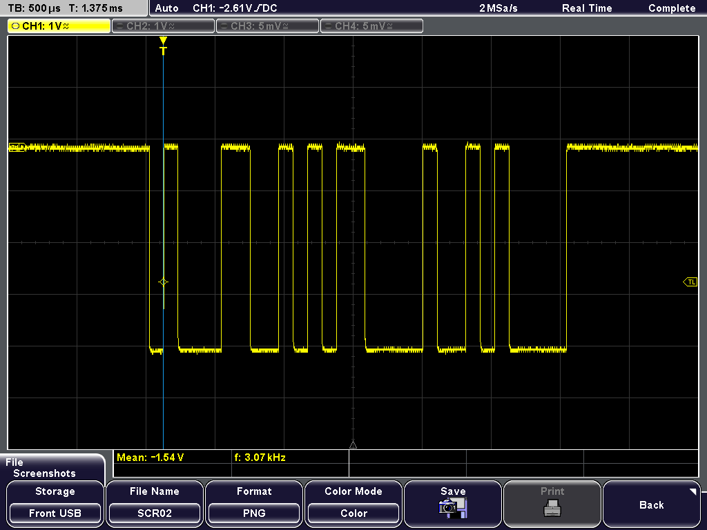
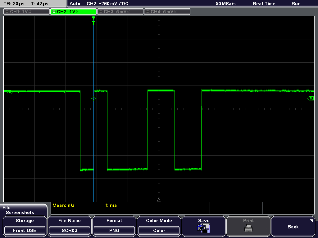
I know that the UART is outputting correctly on UART0 because I can see it on puTTY and when I put it on UART1 to use the external pins I can see on the oscilloscope that data is coming out. However the Xbee does not seem to receive anything on the other side.

I have tired to do this with an Arduino Uno using the "Serial" command and it works fine but it doesn't on the Stellaris even though the settings seem to be the same.

If there is any way you could help me or explain what is going on with the Xbee or Stellaris that would be really appreciated.

Thank you for any help,

Cameron

  • Hello Cameron

    What is the XBee module that you are using?

    Regards
    Amit
  • Cameron Phillips said:
    I can see on the oscilloscope that data is coming out.

    Poster here speaking of his LPad.

    Does that statement not provide best/brightest clue - and solution - all rolled into one?

    Would not a "Scope Capture" of your UART Data Out from the LPad - and a 2nd Capture from the (working) Arduino Data Out - when compared/contrasted - prove most instructive?

    It's doubtful that your radio much cares for data's source - if you can get the 2 data trains to "match" - your radio problem should be resolved...

    Always a common ground between MCU board and radio is required - and in "hook-up haste" - most always neglected and/or improper.   Power for the radio is also critical - the LPad may not be able to fully/properly power itself AND that radio...

  • Hello cb1

    My suspicion would be a 5V-3.3V signalling issue from LPad to the Xbee module.

    Regards
    Amit
  • I am using the Xbee Pro Series 2
  • I suppose I could compare them but how do I adjust them to be the same?
  • I thought that that might be the case so I connected an external 5V supply to the Xbee
  • Cameron Phillips said:
    I suppose I could compare them but how do I adjust them to be the same?

    I suppose I could answer - but then you'd (likely) not follow suggestions - and ask another question.   That's "Krazy Making" - not for me...

  • Hi Cameron,
    This sounds like the classic TX data rate is not matched to the expected RX data rate. Some times we can just try random matching baud rate guesses until they like to play nice with each other.
  • Hello Cameron,

    Can you please attach to the post the specification sheet for the Xbee Pro Series 2, so that all of us are looking at the same document.

    Regards
    Amit
  • Your suggestion was to look at the oscilloscope shots of them both and try to match them but you offered no explanation on how to match them. You do not have to be rude when I am just looking for help but you don't seem to want to offer any serious help or explanations. So thank you for replying at least.
  • I have made both the UART of the Stellaris to have a baud rate of 9600 and the baud rate of the Xbee is 9600 but I do not receive anything still.
  • This is the data sheet for the Xbee that I am using. If you need me to post anymore of my system let me know. Thank you.

    media.digikey.com/.../xbeezbmodule_ds.pdf
  • "Matching" signal levels/rates - most always occurs AFTER one compares and contrasts the requested scope caps.

    Your issue may be:

    • mismatched data levels (your radio may seek 5V - your MCU provides just 3V3)
    • mismatched data rates (your radio may expect one rate and your MCU provides another)

    Either reveals quickly/completely via simple scope caps & comparison.   You stated that you had ONE good scope cap - a 2nd (from your MCU source) is an obvious troubleshooting "next."

    I don't believe rudeness was in play.   I do believe asking a question - w/out responding to suggestion - (may) qualify as improper (and even it's not rude)...

  • Hello Cameron,

    Looks like it is 3.3V signalling at least from the data sheet. But would be a good item to check when powered up in stand alone does the UART TX on the Xbee Pro actually generate 3.3V Idle State.

    Also it would be a good time for you to post the TM4C code as well.

    Regards
    Amit
  • This is my code. I am basically reading the ADC of the pin E2 and trying to output that using UART. In the InitConsole function I have it currently set for output to the computer on UART0 but the commented out is UART1.

    #include "inc/hw_memmap.h"
    #include "inc/hw_types.h"
    #include "driverlib/debug.h"
    #include "driverlib/sysctl.h"
    #include "driverlib/adc.h"
    #include "utils/uartstdio.h"
    #include "utils/uartstdio.c"
    #include "math.h"
    #include "driverlib/gpio.h"

    #ifdef DEBUG
    void
    __error__(char *pcFilename, unsigned long ulLine)
    {
    }
    #endif

    void
    InitConsole(void)
    {
    //
    // Enable GPIO port A which is used for UART0 pins.
    // Enable GPIO port C which is used for UART1 pins

    // SysCtlPeripheralEnable(SYSCTL_PERIPH_GPIOC);
    SysCtlPeripheralEnable(SYSCTL_PERIPH_GPIOA);

    //
    // Configure the pin muxing for UART0 functions on port A0 and A1.
    //

    // GPIOPinConfigure(GPIO_PC4_U1RX);
    // GPIOPinConfigure(GPIO_PC5_U1TX);
    GPIOPinConfigure(GPIO_PA0_U0RX);
    GPIOPinConfigure(GPIO_PA1_U0TX);
    //
    //
    // GPIOPinTypeUART(GPIO_PORTC_BASE, GPIO_PIN_4 | GPIO_PIN_5);
    GPIOPinTypeUART(GPIO_PORTA_BASE, GPIO_PIN_0 | GPIO_PIN_1);
    //
    // Initialize the UART for console I/O.
    //
    UARTStdioInit(0);
    // UARTStdioInit(1);


    }

    int main(void)
    {
    unsigned long ulADC0Value[1];
    volatile unsigned long inst_voltage;


    SysCtlClockSet(SYSCTL_SYSDIV_5|SYSCTL_USE_PLL|SYSCTL_OSC_MAIN|SYSCTL_XTAL_16MHZ);

    SysCtlPeripheralEnable(SYSCTL_PERIPH_ADC0);
    SysCtlADCSpeedSet(SYSCTL_ADCSPEED_250KSPS);
    SysCtlPeripheralEnable(SYSCTL_PERIPH_GPIOE);


    GPIOPinTypeADC(GPIO_PORTE_BASE, GPIO_PIN_2);


    ADCSequenceConfigure(ADC0_BASE, 3, ADC_TRIGGER_PROCESSOR, 0);

    ADCSequenceStepConfigure(ADC0_BASE, 3, 0, ADC_CTL_CH0 | ADC_CTL_IE |ADC_CTL_END);

    ADCSequenceEnable(ADC0_BASE, 3);

    ADCIntClear(ADC0_BASE, 3);


    while(1)
    {
    ADCIntClear(ADC0_BASE, 3);

    ADCProcessorTrigger(ADC0_BASE, 3);

    while(!ADCIntStatus(ADC0_BASE, 3, false))
    {
    }

    ADCSequenceDataGet(ADC0_BASE, 3, ulADC0Value);

    /*******************************************************************
    * This is where I am increasing it by a factor of 10000 so that I can see four decimal places
    *
    *******************************************************************/
    inst_voltage = (ulADC0Value[0]*33000 )/4096; //put in the scaled voltage here

    /********************************************************
    *This works on with the Computer but not Xbee
    ********************************************************/
    UARTprintf("\nAIN1 = %4d:\r", inst_voltage);
    }
    }
  • Hello Cameron

    UARTStdioInit would initialize it to 115200 bps and not 9600 bps.

    Regards
    Amit
  • And would have been quickly/easily recognized "if" poster had (again) connected his scope (as directed).
    Posters (too often) "know best." Except...when they (too often) do not...
  • I do not know best. I will connect it to an Oscilloscope and I will compare the two outputs but oscilloscopes do not grow on trees so it takes me a few days to get my hands on one. Please if you are not going to help keep your snide remarks to yourself. There are other ways than to be disrespectful to get your point across. Get all of the circumstances before you pass judgement.

    Amit-

    I changed the the rate to initialize to 9600 in uartstdio.c as shown below.

    //*****************************************************************************
    //
    //! Initializes the UART console.
    //!
    //! \param ulPortNum is the number of UART port to use for the serial console
    //! (0-2)
    //!
    //! This function will initialize the specified serial port to be used as a
    //! serial console.  The serial parameters will be set to 115200, 8-N-1.
    //! An application wishing to use a different baud rate may call
    //! UARTStdioInitExpClk() instead of this function.
    //!
    //! This function or UARTStdioInitExpClk() must be called prior to using any
    //! of the other UART console functions: UARTprintf() or UARTgets().  In order
    //! for this function to work correctly, SysCtlClockSet() must be called prior
    //! to calling this function.
    //!
    //! It is assumed that the caller has previously configured the relevant UART
    //! pins for operation as a UART rather than as GPIOs.
    //!
    //! \return None.
    //
    //*****************************************************************************
    void
    UARTStdioInit(unsigned long ulPortNum)
    {
        //
        // Pass this call on to the version of the function allowing the baud rate
        // to be specified.
        //
        UARTStdioInitExpClk(ulPortNum, 9600);
    }

  • Hello Cameron,

    That looks correct. To be double sure, can you check the Debugger Window to see if the UARTIBR and UARTFBR registers have the correct divider values for 9600 bps when the system clock is 40MHz.

    Also a snapshot of the TX and RX would be a good idea to inspect.

    Regards
    Amit
  • Cameron Phillips said:
    I can see on the oscilloscope that data is coming out

    Does your past writing (above) - in any manner - convey that your scope is not, "ready/waiting?"   (it does not)

    Now - due to the lack of the (far earlier) requested TM4C UART Scope Cap - your issue has ballooned to 20 posts!

    Might this (unneeded) extra time/effort you've caused (by rejecting earlier guidance) reveal the "real" lack of respect?

  • Ok so I got them both on the Oscilloscope and I can obviously see that the Arduino has much more information being sent and much longer than the Stellaris.

    Both of these boards are just sending a simple 1 on the output.

    This is the Arudino and it has 500us

    This is the Stellaris sending a 1 with the time spacing of 20us

    So I see the problem. However they are both set to 9600 baud rate so I don't know what to do.

    Here is the code for the Arduino I used.


            #include <SoftwareSerial.h>

            SoftwareSerial xbee(2, 3); // RX, TX
            char c = '1';
            int  pingPong = 1;

            void setup()  {
               Serial.begin(9600);
               xbee.begin( 9600 );
            }

            void loop()  {
              xbee.print( c );
             
              //--- display the character just sent on console ---
              Serial.println( c );
              // flash led each time
         if ( pingPong == 0 )
                digitalWrite(13, LOW);
              else
                digitalWrite(13, HIGH);
              pingPong = 1 - pingPong;
              delay( 1000 );
            }

  • Cameron Phillips said:
    Ok so I got them both on the Oscilloscope and I can obviously see that the Arduino has much more information being sent

    OK now - as you note this is immensely helpful - thank you!  

    Now (from memory) at 9600 baud each bit should be ~104µS.   May I suggest that you change from sending your "1" to the hex value 0x55 or 0xAA?   Either of these values produce a repeating pattern of 1-0.   (or 0-1)  Both far more recognizable upon the scope.

    Clearly your data is far faster on the green (Stellaris) trace.   Note that earlier Amit noted your use of the standard I/O would default to 115K Baud - which is more than 10 times your desired (9600) rate.

    You need to read/review the UART API - and discover how to set the baud rate for your MCU...

    And thank you for complying w/the guidance - freely passed - bit earlier.   We note that your Arduino produces just under a 4V output swing, the Stellaris is bit above 3V - this may or may not be an additional issue.   (a good read of the radio spec will reveal the acceptable input signal voltage...)

  • Hello Cameron

    I think I know the problem. The uartstdio.c is using 16MHz to compute the baud rate, while the system clock is 40MHz. This yields a ratio of 2.5

    Now looking at the image for TM4C Transmit, the Start of Frame bit is ~40us which 25Kbps. You asked for a 9600 bps and this is a ratio of ~2.6.

    Check the uartstdio.c for the 9600 bps being set. I bet it is being done with an assumption of system clock or UART clock as 16MHz and not 40MHz. Also I checked the TivaWare 2.1.1.71 uartstdio.c and it seems that UARTStdioInit function is no longer there and instead UARTStdioConfig function is being used.

    Regards
    Amit
  • Hi Amit,

    That's great detail - should prove helpful to poster - and resulted from poster's presentation of TM4C's UART scope cap.

    However - his "working" trace showed signal levels "above" 4V - which you/I know - cannot be matched by TM4C w/out signal buffer... Unknown is the minimum input signal level of his radio - so questions remain...

  • Hello cb1,

    Yes, my view on the Y-axis skewed the X-axis. The poster did mention that with Arduino it works (could it be using 4V signalling, strange), but the Xbee board has spec'ed a good range of 2.7-3.6V as operational range.

    Regards
    Amit
  • We've heard that there are different versions (even counterfeit) of poster's device - so signal level may be of concern.
    From my view of his scope trace - his (reported) working signal (as shown) was well above 3V6 - thus plot thickens...
  • Hello, I'm sorry. I didnt unterdant your code at all.

    I have two questions about it:
    1) are you using the same Uart port for both pc and xbee?

    2)did you write the xbee api codes or are you using some library?

    Thanks,

    Thiago