


Other Parts Discussed in Thread: HALCOGEN
Got a RM57L Hercules launchpad connected to a Seiko/EPSON IMU M-G350 via the MIBSPI3 port.
The plan is to read 500 16bit-words at a time from the IMU using DMA. The mibspi3 element count is 10, frame count is 50.
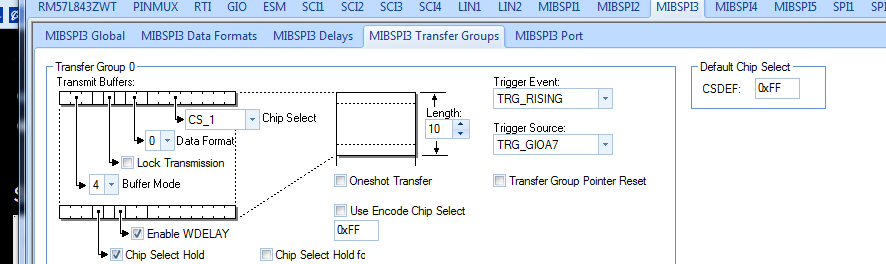
Mibspi3 is set up to trigger on GIOA7. This works fantastic- logic analyzer show all SPI signals as expected.
My problem is the DMA receive buffer does not get filled, and I'm confused what DMA interrupt routine should be used (dmaBTCAInterrupt or dmaGroupANotification) and how to configure it. Can not find good documentation for the libraries generated by halcogen.
How can I set up mibspi3 using DMA to fill up 2x 500 word buffers (ping pong scheme) and make it jump to an interrupt routine when each buffer is full?
(In my test code below, i'm trying to fill one buffer only)
#include "HL_sys_common.h"
/* USER CODE BEGIN (1) */
#include "HL_mibspi.h"
#include "HL_esm.h"
#include "HL_sys_core.h"
#include "HL_sys_dma.h"
#include "HL_system.h"
#include "HL_sys_vim.h"
/* example data Pattern configuration */
#define D_SIZE 500
#define DMA_CH_TX DMA_CH15
#define DMA_CH_RX DMA_CH14
void mibspiEnableInternalLoopback(mibspiBASE_t *mibspi);
void dmaConfigCtrlPacket(uint32 sadd,uint32 dadd,uint32 dsize);
void mibspiDmaConfig(mibspiBASE_t *mibspi,uint32 channel, uint32 txchannel, uint32 rxchannel);
void initIMU();
uint16_t ReadWrite16(uint16_t reg);
void testGetIMUdata();
void Delay(uint32 w);
void dmaInterrupt(void);
void dmaInit();
#pragma SET_DATA_SECTION(".sharedRAM")
uint16 TXDATA[D_SIZE]; /* transmit buffer in sys ram */
uint16 RXDATA[D_SIZE]= {0}; /* receive buffer in sys ram */
#pragma SET_DATA_SECTION()
#define BTCA_INT_CHANNEL 40
bool dma_done = false,
DMA_Comp_Flag=false;
g_dmaCTRL g_dmaCTRLPKT1,
g_dmaCTRLPKT2; /* dma control packet configuration stack */
/* USER CODE END */
/** @fn void main(void)
* @brief Application main function
* @note This function is empty by default.
*
* This function is called after startup.
* The user can use this function to implement the application.
*/
/* USER CODE BEGIN (2) */
/* USER CODE END */
void main(void)
{
/* USER CODE BEGIN (3) */
_enable_IRQ_interrupt_();
mibspiInit();
dmaEnable();
Delay(0xFFFFFF);
// init IMU
initIMU();
TXDATA[0]=FLAG;
TXDATA[1]=TEMP_OUT;
TXDATA[2]=XGYRO_OUT;
TXDATA[3]=YGYRO_OUT;
TXDATA[4]=ZGYRO_OUT;
TXDATA[5]=XACCEL_OUT;
TXDATA[6]=YACCEL_OUT;
TXDATA[7]=ZACCEL_OUT;
TXDATA[8]=DONTCARE;
TXDATA[9]=DONTCARE;
dmaInit();
mibspiTransfer(mibspiREG3,0 );
while (!mibspiIsTransferComplete(mibspiREG3, 0ul));
while(1)
{
if (DMA_Comp_Flag || dma_done)
Delay(0xFFFFF); //set breakpoint here
}
/* loop forever */
/* USER CODE END */
}
/* USER CODE BEGIN (4) */
/** void mibspiEnableLoopback(mibspiBASE_t *mibspi )
*
* enabling internal loopback on mibspix
*/
void dmaInit()
{
// DMA ch1 configuration for TX
dmaReqAssign(DMA_CH_TX,DMA_REQ15);
dmaEnableInterrupt(DMA_CH_TX, BTC, DMA_INTA); /* enable interrupt for block transfer complete */
g_dmaCTRLPKT1.SADD = (uint32)TXDATA; /* source address */
g_dmaCTRLPKT1.DADD = (uint32)&(mibspiRAM3->tx[0].data); /* destination address */
g_dmaCTRLPKT1.CHCTRL = 0; /* channel control */
g_dmaCTRLPKT1.FRCNT = 50; /* frame count */
g_dmaCTRLPKT1.ELCNT = 10;//D_SIZE; /* element count */
g_dmaCTRLPKT1.ELDOFFSET = 4; /* element destination offset */
g_dmaCTRLPKT1.ELSOFFSET = 0; /* element destination offset */
g_dmaCTRLPKT1.FRDOFFSET = 0; /* frame destination offset */
g_dmaCTRLPKT1.FRSOFFSET = 0; /* frame destination offset */
g_dmaCTRLPKT1.PORTASGN = PORTA_READ_PORTB_WRITE;
g_dmaCTRLPKT1.RDSIZE = ACCESS_16_BIT; /* read size */
g_dmaCTRLPKT1.WRSIZE = ACCESS_16_BIT; /* write size */
g_dmaCTRLPKT1.TTYPE = FRAME_TRANSFER ; /* transfer type */
g_dmaCTRLPKT1.ADDMODERD = ADDR_INC1; /* address mode read */
g_dmaCTRLPKT1.ADDMODEWR = ADDR_OFFSET; /* address mode write */
g_dmaCTRLPKT1.AUTOINIT = AUTOINIT_ON; /* autoinit */
dmaSetCtrlPacket(DMA_CH_TX,g_dmaCTRLPKT1);
dmaSetChEnable (DMA_CH_TX, DMA_HW);
//DMA request for RX
dmaReqAssign(DMA_CH_RX, DMA_REQ14);
dmaEnableInterrupt(DMA_CH_RX, BTC, DMA_INTA); /* enable interrupt for block transfer complete */
g_dmaCTRLPKT2.SADD = (uint32)&(mibspiRAM3->rx[0].data); /* source address */
g_dmaCTRLPKT2.DADD = (uint32)RXDATA; /* destination address */
g_dmaCTRLPKT2.CHCTRL = 0; /* channel control */
g_dmaCTRLPKT2.FRCNT = 50; /* frame count */
g_dmaCTRLPKT2.ELCNT = 10;//D_SIZE; /* element count */
g_dmaCTRLPKT2.ELDOFFSET = 0; /* element destination offset */
g_dmaCTRLPKT2.ELSOFFSET = 4; /* element destination offset */
g_dmaCTRLPKT2.FRDOFFSET = 0; /* frame destination offset */
g_dmaCTRLPKT2.FRSOFFSET = 0; /* frame destination offset */
g_dmaCTRLPKT2.PORTASGN = PORTB_READ_PORTA_WRITE;
g_dmaCTRLPKT2.RDSIZE = ACCESS_16_BIT; /* read size */
g_dmaCTRLPKT2.WRSIZE = ACCESS_16_BIT; /* write size */
g_dmaCTRLPKT2.TTYPE = FRAME_TRANSFER ; /* transfer type */
g_dmaCTRLPKT2.ADDMODERD = ADDR_OFFSET; /* address mode read */
g_dmaCTRLPKT2.ADDMODEWR = ADDR_INC1; /* address mode write */
g_dmaCTRLPKT2.AUTOINIT = AUTOINIT_ON; /* autoinit */
dmaSetCtrlPacket(DMA_CH_RX,g_dmaCTRLPKT2);
dmaSetChEnable(DMA_CH_RX, DMA_HW);
/* upto 32 control packets are supported. */
mibspiDmaConfig(mibspiREG3,0,0,1); //mibspi3[0], and mibspi3[1]
mibspiEnableGroupNotification(mibspiREG3,0,1);
}
/** void mibspiDmaConfig(mibspiBASE_t *mibspi,uint32 channel, uint32 txchannel, uint32 rxchannel)
*
* configuring mibspi dma with
*
* channel > mibspi dma channel number
* txchannel > transmit channel dedicated for mibspi
* rxchannel > receive channel dedicated for mibspi
*/
void mibspiDmaConfig(mibspiBASE_t *mibspi,uint32 channel, uint32 txchannel, uint32 rxchannel)
{
uint32 bufid = D_SIZE - 1;
uint32 icount = 0;
/* setting transmit and receive channels */
mibspi->DMACTRL[channel] |= (((rxchannel<<4)|txchannel) << 16);
/* enabling transmit and receive dma */
mibspi->DMACTRL[channel] |= 0x8000C000;
/* setting Initial Count of DMA transfers and the buffer utilized for DMA transfer */
mibspi->DMACTRL[channel] |= (icount << 8) |(bufid<<24);
}

