This thread has been locked.

If you have a related question, please click the "Ask a related question" button in the top right corner. The newly created question will be automatically linked to this question.

Timer Capture T3CCP0 for RC6

Good day,

I have an infrared sensor which implements the protocol RC6.

I am using the board EK-TM4C1295NCPD.

I connected the sensor data line at PM2.

According with spmu365b.pdf, PM2 implements T3CCP0.

T3CCP0 corresponds to Timer3-TimerA.

I want only to detect the push of the button on a remote controller which means that I expect the TIMER_3A to throw an interrupt.

The code is simple:

    GPIOPinConfigure(GPIO_PM2_T3CCP0);
    GPIOPinTypeTimer(GPIO_PORTM_BASE, GPIO_PIN_5);

    SysCtlPeripheralEnable(SYSCTL_PERIPH_TIMER3);
    TimerClockSourceSet(TIMER3_BASE, TIMER_CLOCK_SYSTEM);
    TimerConfigure(TIMER3_BASE, TIMER_CFG_A_CAP_COUNT);
    TimerLoadSet(TIMER3_BASE, TIMER_A, 4);
    TimerControlEvent(TIMER3_BASE, TIMER_A, TIMER_EVENT_POS_EDGE);

    TimerIntEnable(TIMER3_BASE, TIMER_CAPA_EVENT);
    IntEnable(INT_TIMER3A);
    IntMasterEnable();

    TimerEnable(TIMER3_BASE, TIMER_A);


In .cfg file I implemented 51 hardware interrupt which corresponds to: INT_TIMER3A:

Program.global.hwiTimer2A = Hwi.create(51, "&hwiTimer2AFxn", hwi0Params);

The hardware interrupt function:

extern "C" void hwiTimer2AFxn(void)
{
    TimerIntClear(TIMER3_BASE, TIMER_CAPA_EVENT);

    Swi_post(swiTimer2A);
}

And the application starts but the debug does not hit the break point in interrupt function.

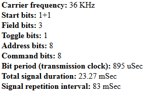
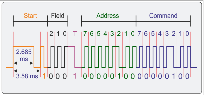
Here is the specification of RC6:

Can you please help me?

Thanks

Horea

  • Hello Horea

    The following line is incorrect.

    GPIOPinTypeTimer(GPIO_PORTM_BASE, GPIO_PIN_5);

    Since the pin is PM2 the line should be

    GPIOPinTypeTimer(GPIO_PORTM_BASE, GPIO_PIN_2);

    Regards
    Amit
  • The code to trigger the message coming from remote control for infrared RC6:

    int main(void)
    {
    Board_initGeneral();
    Board_initGPIO();

    SysCtlPeripheralEnable(SYSCTL_PERIPH_TIMER3);
    TimerClockSourceSet(TIMER3_BASE, TIMER_CLOCK_SYSTEM);

    GPIOPinConfigure(GPIO_PM2_T3CCP0);
    GPIOPinTypeTimer(GPIO_PORTM_BASE, GPIO_PIN_2);

    TimerConfigure(TIMER3_BASE, TIMER_CFG_SPLIT_PAIR | TIMER_CFG_A_CAP_COUNT);
    TimerLoadSet(TIMER3_BASE, TIMER_A, 4);
    TimerMatchSet(TIMER3_BASE, TIMER_A, 0);
    TimerControlEvent(TIMER3_BASE, TIMER_A, TIMER_EVENT_BOTH_EDGES);

    TimerIntEnable(TIMER3_BASE, TIMER_CAPA_MATCH);
    IntEnable(INT_TIMER3A);
    IntMasterEnable();


    TimerEnable(TIMER3_BASE, TIMER_A);

    BIOS_start();
    }

    extern "C" void hwiTimer2AFxn(void)
    {
        TimerIntClear(TIMER3_BASE, TIMER_CAPA_MATCH);

        Swi_post(swiTimer2A);
    }

    extern "C" void swiTimer2AFxn(void)
    {
        GPIO_toggle(Board_LED0);
        Log_info0("swiTimer2AFxn");

        TimerEnable(TIMER3_BASE, TIMER_A);
    }

    And you know that in .cfg file you should create a hardware interrupt for INT_TIMER3A which is basically the value 51.

    The problem is that it gets only the first interrupt.

    I think something should be reset also after the first interrupt.

    I am checking and come back with a post.

  • Hello Horea

    In Capture Match mode, when the capture is completed the Enable bit must be set again. From the data sheet

    After the match value is reached in down-count mode, the counter is then reloaded using the value
    in GPTMTnILR and GPTMTnPR registers, and stopped because the GPTM automatically clears
    the TnEN bit in the GPTMCTL register. Once the event count has been reached, all further events
    are ignored until TnEN is re-enabled by software. In up-count mode, the timer is reloaded with 0x0
    and continues counting.

    Regards
    Amit
  • Thank you Amit,

    I added to the code the software interrupt function which re-enable the timer.
    I tested and it is working ok.

    Regards
    Horea
  • Hello Horea

    And also I have posted a response to the other issue of interrupt

    Regards
    Amit