Other Parts Discussed in Thread: TM4C123GH6PM
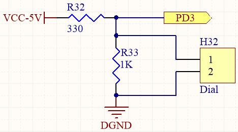
I am using an ADC on the TM4C123GH6PM Launchpad. I have constructed a voltage divider circuit to allow for a dial (potentiometer) to adjust the input voltage seen at the ADC pin (PD3), as shown here:

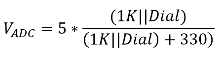
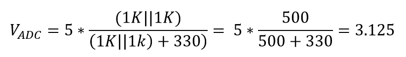
The potentiometer has a range of 0 to 1k ohms. This circuit allows me to adjust the ADC input voltage between 0V and about 3V.
In the testing of my project I find that about 50% of the time when I turn my system on, I get a voltage of 3.75V at the input of the ADC pin. I have tested the reostat and it seems to be working fine. The only explanation for this can be that the ADC is drawing in way more current than it should be. How can this be? Am I not protecting my ADC properly? Why does it work sometimes and not others? Do I not have the ADC configured properly? Here is my configuration code:
void ConfigADCs(){
SysCtlPeripheralEnable(SYSCTL_PERIPH_ADC1); // Enable Peripheral Clocks
SysCtlDelay(80);
ADCSequenceConfigure(ADC1_BASE, 3, ADC_TRIGGER_PROCESSOR, 0);
ADCSequenceStepConfigure(ADC1_BASE, 3, 0, ADC_CTL_CH4 | ADC_CTL_IE | ADC_CTL_END); // Enable pin PD3 for AIN4
// Hardware Averaging of 64 samples
// sites.google.com/.../hardware-average
ADCHardwareOversampleConfigure(ADC1_BASE, 64);
ADCSequenceEnable(ADC1_BASE, 3);
ADCIntClear(ADC1_BASE, 3);
}
Could it be the bypass capacitors that I have in line with the microcontroller as shown in the figure below?

Any help or suggestions are greatly appreciated! Thank you!
Marshall