This thread has been locked.

If you have a related question, please click the "Ask a related question" button in the top right corner. The newly created question will be automatically linked to this question.

UART

Other Parts Discussed in Thread: TM4C1294NCPDT

Hello.

Iam traying receive more of 16 bytes by the UART,  I am sending 20 bytes buy a terminal, but only receive the first 16....

this is my code:

----------------------------------------------------------------------------------------------------------------

After that  I configure the UART

uint8_t RX_BUFFER[20]; //array for save bytes

int p=0;

while((UART0_FR_R&0x0010)!=0); Loop for wait, a byte was received by terminal

RX_BUFFER[p++]=UART0_DR_R&0xFF;;

-------------------------------------------------------------------------------------------------------------------

I dont know why save only 16

  • Hello Oscar,

    The forum has mention of this issue, but all tests to reproduce the same show that UART does work as expected. BTW, in the code where is UART read happening? Is it main code or Interrupt, details missing

    Regards
    Amit
  • where UART is read, is the main code.. why ?????
  • Hello Oscar

    The while loop checks if the RXFIFO is empty or not. Once it has data it reads the byte in the RX_BUFFER. Then how does it go to read the next byte?

    while((UART0_FR_R&0x0010)!=0); Loop for wait, a byte was received by terminal

    RX_BUFFER[p++]=UART0_DR_R&0xFF;;

    Regards
    Amit
  • SORRY. I forgot something

    while((UART0_FR_R&0x0010)!=0); Loop for wait, a byte was received by terminal
    while(p<20){///////////////////////////////////////
    RX_BUFFER[p++]=UART0_DR_R&0xFF;
    }

    with the while that I just added , I can read only the first 16 and oviously I want to read 20
  • You wait for the first byte, I see no evidence you wait for subsequent bytes. I see no evidence that you actually check that you have anything other than the first byte available to read.

    Robert
  • Hello Robert

    Likewise. There is no check of Data in Buffer Flag in UARTFR register

    Regards
    Amit
  • With this code I can receive 16 bits,, but not 20 that I want ro receive
    The proble is that I don't know what to do..... Could you help me?? Only I want to know if I neeed to ask(polear) for anyBIT in the register UART0_FR_R, o what I have to do?
    SORRY, my english is too basic
  • Suggest you look at the TIVAWare functions Oscar. Even if you don't use them directly looking at the source will be useful.

    Robert
  • EXCUSE ME. DO YOU SPEAK SPANISH???
  • Hello Oscar,

    No, I don't. But lets see your entire UART code to be sure that is a caveat or not.

    Regards
    Amit
  • This is my UART code:


    #include <stdint.h>
    #include <stdbool.h>
    #include "inc/tm4c1294ncpdt.h"
    #include "driverlib/rom_map.h"
    #include "driverlib/sysctl.h"
    #include "driverlib/gpio.h"

    uint8_t RX_BUFFER[20];

    UART0_INI(void){
    SYSCTL_RCGCUART_R |=0X41; //enable uart0 and uart6
    SYSCTL_RCGCGPIO_R |=0X3021; //enable ports A,F,N,P
    UART0_CTL_R &=~0X0001; //disble uart for configue it
    UART0_IBRD_R =520 ; //IBDR=int(120000000/16*14400))
    UART0_FBRD_R =53 ; //FBRD= round(0.8333*64 )
    UART0_LCRH_R =0X0070; //enable FIFO and configure UART
    UART0_CTL_R= 0X0301 ; //enable RXE, TXE Y UART
    GPIO_PORTA_AHB_PCTL_R = 0X00000011;//
    GPIO_PORTA_AHB_AMSEL_R &= ~0X03; //disable analogic function in PA0 and PA1
    GPIO_PORTA_AHB_AFSEL_R |= 0X03; //enable alternate funcion in PA0 and PA1
    GPIO_PORTA_AHB_DEN_R |= 0X03; //enable digital function
    }

    int main(){
    uint32_t g_ui32SysClock;
    g_ui32SysClock = MAP_SysCtlClockFreqSet((SYSCTL_XTAL_25MHZ | SYSCTL_OSC_MAIN | SYSCTL_USE_PLL | SYSCTL_CFG_VCO_480), 120000000);

    p=0;
    UART0_INI();
    SysCtlDelay(40000000);

    while((UART0_FR_R&0x0010)!=0); Loop for wait, a byte was received by terminal
    while(p<20){
    RX_BUFFER[p++]=UART0_DR_R&0xFF;
    }
    while(1);loop
    }


    Only can receive 16 byts, no more....
  • This is my UART code

    #include <stdint.h>
    #include <stdbool.h>
    #include "inc/tm4c1294ncpdt.h"
    #include "driverlib/rom_map.h"
    #include "driverlib/sysctl.h"
    #include "driverlib/gpio.h"

    uint8_t RX_FO[512];

    UART0_INI(void){
    SYSCTL_RCGCUART_R |=0X41; //enable UART0, UART6
    SYSCTL_RCGCGPIO_R |=0X3021; //enable ports A,F,N,P
    UART0_CTL_R &=~0X0001; //disable UART0
    UART0_IBRD_R =520 ; //IBDR=int(120000000/16*14400))
    UART0_FBRD_R =53 ; //FBRD= round(0.8333*64 )
    UART0_LCRH_R =0X0070; //enable FIFO
    UART0_CTL_R= 0X0301 ; //enable RXE, TXE Y UART
    GPIO_PORTA_AHB_PCTL_R = 0X00000011;//enable PA0 and PA1 as Tx,Rx
    GPIO_PORTA_AHB_AMSEL_R &= ~0X03; //disable analogic function in PA0and PA1
    GPIO_PORTA_AHB_AFSEL_R |= 0X03; //enable alternate function in PA0, PA1
    GPIO_PORTA_AHB_DEN_R |= 0X03; //enable digital function in PA0,PA1
    }

    int main(){
    uint32_t g_ui32SysClock
    g_ui32SysClock = MAP_SysCtlClockFreqSet((SYSCTL_XTAL_25MHZ | SYSCTL_OSC_MAIN | SYSCTL_USE_PLL | SYSCTL_CFG_VCO_480), 120000000);
    int p=0;
    UART0_INI();
    SysCtlDelay(40000000);

    while((UART0_FR_R&0x0010)!=0); Loop for wait, a byte was received by terminal
    while(p<20){///////////////////////////////////////
    RX_BUFFER[p++]=UART0_DR_R&0xFF;
    }


    while(1);
    }


    Only can receibe 16 bbytes
  • Hello Oscar,

    I would suggest

    p=0;
    while(p != 20)
    {
    while((UART0_FR_R&0x0010)!=0);
    RX_BUFFER[p++]=UART0_DR_R&0xFF;
    }
  • THANKE YOU.. I'll try..
  • Iam trying receive more of the 16bytes bytes because Iam using the camera C1098, the problem is when I want to receive  521bytes of a photo..

    I had success to communicate with the camera,  The communication with the camara is not difficult, only I send to the camera a command and the camera respond me.

    I send packages of 6bytes and the camera respond me with package of 6bytes  but when I want to receive the photo I can't receive completely ..

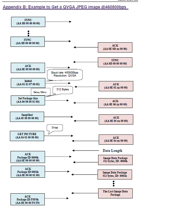
    this is the protocol.

    I did a function to receive the packages,:

    RECEIVE_COMMANDS(uint8_t arrayRX[],int o){
       int t=0;
       while(t<o){
              while((UART6_FR_R&0x0010)!=0);
              arrayRX[t]=UART6_DR_R&0xFF;
              UART0_DR_R=arrayRX[t++];
        }
    }

    with this function I can receive the packages of 6bytes, but no more of 16bytes

  • oscar merida said:
              UART0_DR_R=arrayRX[t++];

    This would be unusual. Also it is not what is in the chart. Usually large blocks of data are not echoed.

    oscar merida said:
    with this function I can receive the packages of 6bytes, but no more of 16bytes

    Explain what you mean

    What does the function that calls RECEIVE_COMMANDS look like?

    Robert

  • Do you speak spanish???
    sorry, Is dificult to me
  • Hello Oscar,

    Is this uCAM II, camera?

    Regards
    Amit
  • lo siento, no entiendo español. tal vez usted puede utilizar el traductor de google?
  • C1098 is VGA camera module performs as a JPEG compressed still camera that can be
    attached to a wireless or PDA host
  • With the function RECEIVE_COMMANDS only wait for there ia a byte in the FIFO, if there is a byte in the FIFO I read the register UART6_DR_R and that value is assigned to arrayRX.
    first I declared the array
    uint8_t RX_BUFFER0[6];
    after call the function
    RECEIVE_COMMANDS(RX_BUFFER0,6);
    finally the values are in the array

    sorry for mi english..
  • Hello..
    Could you help me!!!
  • excuse me...
    you mean if I 'm using this camera
  • Hello Oscar,

    May be I can share a rudimentary code with you next week for another camera which had BMP capability over serial port. You may use the same to build the application you have in mind.

    Regards
    Amit
  • THANKE YOU, but I need to use this camera because is for the school ans it is obligatory.
  • Hello Oscar

    Here is a code base that I used for a serial port camera called uCAM II which I interfaced with DK-TM4C129x. It may not be an exact fit but will give you an idea based on the uCAM-II data sheet and the code as to how to establish communication.

    #include <stdint.h>
    #include <stdbool.h>
    #include "inc/hw_memmap.h"
    #include "inc/hw_types.h"
    #include "inc/hw_gpio.h"
    #include "inc/hw_sysctl.h"
    #include "inc/hw_epi.h"
    #include "inc/hw_ints.h"
    #include "inc/hw_nvic.h"
    #include "inc/hw_uart.h"
    #include "inc/hw_lcd.h"
    #include "driverlib/debug.h"
    #include "driverlib/fpu.h"
    #include "driverlib/gpio.h"
    #include "driverlib/rom.h"
    #include "driverlib/rom_map.h"
    #include "driverlib/interrupt.h"
    #include "driverlib/pin_map.h"
    #include "driverlib/sysctl.h"
    #include "driverlib/uart.h"
    #include "driverlib/lcd.h"
    #include "drivers/kentec320x240x16_ssd2119.h"
    #include "utils/uartstdio.h"
    
    //*****************************************************************************
    //
    // Number of bytes to send and receive.
    //
    //*****************************************************************************
    #define NUM_SSI_DATA            3
    
    volatile uint32_t gui32RAWPixel[38400];
    
    //*****************************************************************************
    //
    // This function sets up UART0 to be used for a console to display information
    // as the example is running.
    //
    //*****************************************************************************
    void
    InitConsole(void)
    {
        //
        // Enable GPIO port A which is used for UART0 pins.
        // TODO: change this to whichever GPIO port you are using.
        //
        SysCtlPeripheralEnable(SYSCTL_PERIPH_GPIOA);
    
        //
        // Configure the pin muxing for UART0 functions on port A0 and A1.
        // This step is not necessary if your part does not support pin muxing.
        // TODO: change this to select the port/pin you are using.
        //
        GPIOPinConfigure(GPIO_PA0_U0RX);
        GPIOPinConfigure(GPIO_PA1_U0TX);
    
        //
        // Enable UART0 so that we can configure the clock.
        //
        SysCtlPeripheralEnable(SYSCTL_PERIPH_UART0);
    
        //
        // Use the internal 16MHz oscillator as the UART clock source.
        //
        UARTClockSourceSet(UART0_BASE, UART_CLOCK_PIOSC);
    
        //
        // Select the alternate (UART) function for these pins.
        // TODO: change this to select the port/pin you are using.
        //
        GPIOPinTypeUART(GPIO_PORTA_BASE, GPIO_PIN_0 | GPIO_PIN_1);
    
        //
        // Initialize the UART for console I/O.
        //
        UARTStdioConfig(0, 115200, 16000000);
    }
    
    //*****************************************************************************
    //
    // Configure SSI3 in master Freescale (SPI) mode.  This example will send out
    // 3 bytes of data, then wait for 3 bytes of data to come in.  This will all be
    // done using the polling method.
    //
    //*****************************************************************************
    int
    main(void)
    {
        uint32_t ui32SysClockFreq;
        uint32_t ui32Index, ui32DelayLoop;
        uint32_t ui32UARTCharArray[12], ui32NumberofBytes;
        uint32_t ui32Row, ui32Col;
        bool     bBreakLoop;
    
        //
        // Set the clocking to run directly from the external crystal/oscillator.
        // TODO: The SYSCTL_XTAL_ value must be changed to match the value of the
        // crystal on your board.
        //
        ui32SysClockFreq = SysCtlClockFreqSet((SYSCTL_XTAL_25MHZ |
                                               SYSCTL_OSC_MAIN |
                                               SYSCTL_USE_PLL |
                                               SYSCTL_CFG_VCO_480), 120000000);
        //
        // Set up the serial console to use for displaying messages.  This is
        // just for this example program and is not needed for SSI operation.
        //
        InitConsole();
    
        //
        // Display the setup on the console.
        //
        UARTprintf("TM4C129 -> uCAMII Example\n");
    
        //
        // The UART1 and GPIOB peripheral must be enabled for use.
        //
        SysCtlPeripheralEnable(SYSCTL_PERIPH_GPIOB);
        SysCtlPeripheralEnable(SYSCTL_PERIPH_UART1);
    
        //
        // Configure the pin muxing for UART1 functions on port B0 and B1.
        // This step is not necessary if your part does not support pin muxing.
        // TODO: change this to select the port/pin you are using.
        //
        GPIOPinConfigure(GPIO_PB0_U1RX);
        GPIOPinConfigure(GPIO_PB1_U1TX);
    
        //
        // Configure the GPIO settings for the UART pins.  This function also gives
        // control of these pins to the UART hardware.  Consult the data sheet to
        // see which functions are allocated per pin.
        // The pins are assigned as follows:
        //      PB0 - UART1RX
        //      PB1 - UART1TX
        //
        GPIOPinTypeUART(GPIO_PORTB_BASE, GPIO_PIN_1 |
                       GPIO_PIN_0);
    
        //
        // Configure and enable the UART port for 115200 bps, 8N1 format
        //
        UARTConfigSetExpClk(UART1_BASE, ui32SysClockFreq, 57600,(UART_CONFIG_PAR_NONE | UART_CONFIG_STOP_ONE |
                	UART_CONFIG_WLEN_8));
    
        //
        // Enable UART Receive Interrupt
        //
    
        //
        // Enable the UART1 module.
        //
        UARTEnable(UART1_BASE);
    
        //
        // Initialize LCD
        //
        //
        // PF6-7/PJ6/PS4-5/PR0-7 are used for the LCD.
        //
        SysCtlPeripheralEnable(SYSCTL_PERIPH_GPIOF);
        SysCtlPeripheralEnable(SYSCTL_PERIPH_GPIOJ);
        SysCtlPeripheralEnable(SYSCTL_PERIPH_GPION);
        SysCtlPeripheralEnable(SYSCTL_PERIPH_GPIOR);
        SysCtlPeripheralEnable(SYSCTL_PERIPH_GPIOS);
        SysCtlPeripheralEnable(SYSCTL_PERIPH_GPIOT);
        SysCtlDelay(10);
    
        GPIOPinConfigure(GPIO_PJ6_LCDAC);
        GPIOPinConfigure(GPIO_PR0_LCDCP);
        GPIOPinConfigure(GPIO_PR1_LCDFP);
        GPIOPinConfigure(GPIO_PR2_LCDLP);
        GPIOPinConfigure(GPIO_PR4_LCDDATA00);
        GPIOPinConfigure(GPIO_PF7_LCDDATA02);
        GPIOPinConfigure(GPIO_PR5_LCDDATA01);
        GPIOPinConfigure(GPIO_PR3_LCDDATA03);
        GPIOPinConfigure(GPIO_PR6_LCDDATA04);
        GPIOPinConfigure(GPIO_PR7_LCDDATA05);
        GPIOPinConfigure(GPIO_PS4_LCDDATA06);
        GPIOPinConfigure(GPIO_PS5_LCDDATA07);
        GPIOPinConfigure(GPIO_PS6_LCDDATA08);
        GPIOPinConfigure(GPIO_PS7_LCDDATA09);
        GPIOPinConfigure(GPIO_PT0_LCDDATA10);
        GPIOPinConfigure(GPIO_PT1_LCDDATA11);
        GPIOPinConfigure(GPIO_PN7_LCDDATA12);
        GPIOPinConfigure(GPIO_PN6_LCDDATA13);
        GPIOPinConfigure(GPIO_PJ2_LCDDATA14);
        GPIOPinConfigure(GPIO_PJ3_LCDDATA15);
        GPIOPinTypeGPIOOutput(GPIO_PORTF_BASE, GPIO_PIN_6);
        GPIOPinWrite(GPIO_PORTF_BASE, GPIO_PIN_6, GPIO_PIN_6);
        GPIOPinTypeLCD(GPIO_PORTF_BASE, GPIO_PIN_7);
        GPIOPinTypeLCD(GPIO_PORTJ_BASE, GPIO_PIN_2 | GPIO_PIN_3 | GPIO_PIN_6);
        GPIOPinTypeLCD(GPIO_PORTN_BASE, GPIO_PIN_6 | GPIO_PIN_7);
        GPIOPinTypeLCD(GPIO_PORTR_BASE,
                           (GPIO_PIN_0 | GPIO_PIN_1 | GPIO_PIN_2 | GPIO_PIN_3 |
                            GPIO_PIN_4 | GPIO_PIN_5 | GPIO_PIN_6 | GPIO_PIN_7));
        GPIOPinTypeLCD(GPIO_PORTS_BASE, GPIO_PIN_4 | GPIO_PIN_5 | GPIO_PIN_6 | GPIO_PIN_7);
        GPIOPinTypeLCD(GPIO_PORTT_BASE, GPIO_PIN_0 | GPIO_PIN_1);
    
    #if 1
        bBreakLoop = false;
    
        for(ui32Index=0;ui32Index<60;ui32Index++)
        {
        	UARTCharPut(UART1_BASE,0xAA);
        	UARTCharPut(UART1_BASE,0x0D);
        	UARTCharPut(UART1_BASE,0x00);
        	UARTCharPut(UART1_BASE,0x00);
        	UARTCharPut(UART1_BASE,0x00);
        	UARTCharPut(UART1_BASE,0x00);
        	for(ui32DelayLoop=0;ui32DelayLoop<200000;ui32DelayLoop++)
        	{
        		if(UARTCharsAvail(UART1_BASE))
        		{
        			ui32UARTCharArray[0] = UARTCharGet(UART1_BASE);
        			ui32UARTCharArray[1] = UARTCharGet(UART1_BASE);
        			ui32UARTCharArray[2] = UARTCharGet(UART1_BASE);
        			ui32UARTCharArray[3] = UARTCharGet(UART1_BASE);
        			ui32UARTCharArray[4] = UARTCharGet(UART1_BASE);
        			ui32UARTCharArray[5] = UARTCharGet(UART1_BASE);
        			ui32UARTCharArray[6] = UARTCharGet(UART1_BASE);
        			ui32UARTCharArray[7] = UARTCharGet(UART1_BASE);
        			ui32UARTCharArray[8] = UARTCharGet(UART1_BASE);
        			ui32UARTCharArray[9] = UARTCharGet(UART1_BASE);
        			ui32UARTCharArray[10] = UARTCharGet(UART1_BASE);
        			ui32UARTCharArray[11] = UARTCharGet(UART1_BASE);
        			bBreakLoop = true;
        			break;
        		}
        	}
        	if(bBreakLoop)
        	{
            	UARTCharPut(UART1_BASE,0xAA);
            	UARTCharPut(UART1_BASE,0x0E);
            	UARTCharPut(UART1_BASE,0x0D);
            	UARTCharPut(UART1_BASE,0x00);
            	UARTCharPut(UART1_BASE,0x00);
            	UARTCharPut(UART1_BASE,0x00);
            	break;
        	}
        }
    
        UARTprintf("UCAMII Response : ");
        for(ui32Index=0;ui32Index<6;ui32Index++)
        {
            UARTprintf("%02x",ui32UARTCharArray[ui32Index]);
        }
        UARTprintf("\n");
        UARTprintf("UCAMII Response : ");
        for(ui32Index=6;ui32Index<12;ui32Index++)
        {
            UARTprintf("%02x",ui32UARTCharArray[ui32Index]);
        }
        UARTprintf("\n");
    
    #if 1
        //
        // Set New Baud Rate
        //
    	UARTCharPut(UART1_BASE,0xAA);
    	UARTCharPut(UART1_BASE,0x07);
    	UARTCharPut(UART1_BASE,0x00);
    	UARTCharPut(UART1_BASE,0x00);
    	UARTCharPut(UART1_BASE,0x00);
    	UARTCharPut(UART1_BASE,0x00);
    	ui32UARTCharArray[0] = UARTCharGet(UART1_BASE);
    	ui32UARTCharArray[1] = UARTCharGet(UART1_BASE);
    	ui32UARTCharArray[2] = UARTCharGet(UART1_BASE);
    	ui32UARTCharArray[3] = UARTCharGet(UART1_BASE);
    	ui32UARTCharArray[4] = UARTCharGet(UART1_BASE);
    	ui32UARTCharArray[5] = UARTCharGet(UART1_BASE);
        UARTprintf("UCAMII Response to Baud Rate  : ");
        for(ui32Index=0;ui32Index<6;ui32Index++)
        {
            UARTprintf("%02x",ui32UARTCharArray[ui32Index]);
        }
        UARTprintf("\n");
        while(UARTBusy(UART1_BASE));
    
        UARTConfigSetExpClk(UART1_BASE, ui32SysClockFreq, 3686400,(UART_CONFIG_PAR_NONE | UART_CONFIG_STOP_ONE |
                	UART_CONFIG_WLEN_8));
    #endif
    
        //
        // Begin Data Acquisition
        //
    	UARTCharPut(UART1_BASE,0xAA);
    	UARTCharPut(UART1_BASE,0x01);
    	UARTCharPut(UART1_BASE,0x00);
    	UARTCharPut(UART1_BASE,0x06);
    	UARTCharPut(UART1_BASE,0x03);
    	UARTCharPut(UART1_BASE,0x00);
        while(!UARTCharsAvail(UART1_BASE));
    	ui32UARTCharArray[0] = UARTCharGet(UART1_BASE);
    	ui32UARTCharArray[1] = UARTCharGet(UART1_BASE);
    	ui32UARTCharArray[2] = UARTCharGet(UART1_BASE);
    	ui32UARTCharArray[3] = UARTCharGet(UART1_BASE);
    	ui32UARTCharArray[4] = UARTCharGet(UART1_BASE);
    	ui32UARTCharArray[5] = UARTCharGet(UART1_BASE);
        UARTprintf("UCAMII Response to Initial    : ");
        for(ui32Index=0;ui32Index<6;ui32Index++)
        {
            UARTprintf("%02x",ui32UARTCharArray[ui32Index]);
        }
        UARTprintf("\n");
    
        while(1)
        {
    	UARTCharPut(UART1_BASE,0xAA);
    	UARTCharPut(UART1_BASE,0x05);
    	UARTCharPut(UART1_BASE,0x01);
    	UARTCharPut(UART1_BASE,0x00);
    	UARTCharPut(UART1_BASE,0x00);
    	UARTCharPut(UART1_BASE,0x00);
        while(!UARTCharsAvail(UART1_BASE));
    	ui32UARTCharArray[0] = UARTCharGet(UART1_BASE);
    	ui32UARTCharArray[1] = UARTCharGet(UART1_BASE);
    	ui32UARTCharArray[2] = UARTCharGet(UART1_BASE);
    	ui32UARTCharArray[3] = UARTCharGet(UART1_BASE);
    	ui32UARTCharArray[4] = UARTCharGet(UART1_BASE);
    	ui32UARTCharArray[5] = UARTCharGet(UART1_BASE);
    #if 0
    	UARTprintf("UCAMII Response to Snapshot   : ");
        for(ui32Index=0;ui32Index<6;ui32Index++)
        {
            UARTprintf("%02x",ui32UARTCharArray[ui32Index]);
        }
        UARTprintf("\n");
    #endif
    
    	UARTCharPut(UART1_BASE,0xAA);
    	UARTCharPut(UART1_BASE,0x04);
    	UARTCharPut(UART1_BASE,0x01);
    	UARTCharPut(UART1_BASE,0x00);
    	UARTCharPut(UART1_BASE,0x00);
    	UARTCharPut(UART1_BASE,0x00);
        while(!UARTCharsAvail(UART1_BASE));
    	ui32UARTCharArray[0] = UARTCharGet(UART1_BASE);
    	ui32UARTCharArray[1] = UARTCharGet(UART1_BASE);
    	ui32UARTCharArray[2] = UARTCharGet(UART1_BASE);
    	ui32UARTCharArray[3] = UARTCharGet(UART1_BASE);
    	ui32UARTCharArray[4] = UARTCharGet(UART1_BASE);
    	ui32UARTCharArray[5] = UARTCharGet(UART1_BASE);
    #if 0
    	UARTprintf("UCAMII Response to Size       : ");
        for(ui32Index=0;ui32Index<6;ui32Index++)
        {
            UARTprintf("%02x",ui32UARTCharArray[ui32Index]);
        }
        UARTprintf("\n");
    #endif
    
        ui32NumberofBytes = ((ui32UARTCharArray[3] << 16) | (ui32UARTCharArray[4] << 8) | ui32UARTCharArray[5] << 16);
    
    #if 0
        UARTprintf("UCAMII Response to Pixel Byte : %x",ui32NumberofBytes);
        UARTprintf("\n");
    #endif
    
        for(ui32Row=0;ui32Row<120;ui32Row++)
        {
        	for(ui32Col=0;ui32Col<160;ui32Col++)
        	{
            	gui32RAWPixel[(2*ui32Row*160)+ui32Col] = (UARTCharGet(UART1_BASE) << 8);
            	gui32RAWPixel[(2*ui32Row*160)+ui32Col] |=  UARTCharGet(UART1_BASE);
            	gui32RAWPixel[(2*ui32Row*160)+ui32Col] |=  (gui32RAWPixel[(2*ui32Row*160)+ui32Col] << 16);
            	gui32RAWPixel[((2*ui32Row)+1)*160+ui32Col] =  gui32RAWPixel[(2*ui32Row*160)+ui32Col];
        	}
        }
    
    #if 0
        for(ui32Index=0;ui32Index<(ui32NumberofBytes/2);ui32Index++)
        {
        	gui32RAWPixel[ui32Index] = (UARTCharGet(UART1_BASE) << 8);
        	gui32RAWPixel[ui32Index] |=  UARTCharGet(UART1_BASE);
        	gui32RAWPixel[ui32Index] |=  (gui32RAWPixel[ui32Index] << 16);
        	gui32RAWPixel[ui32Index] =  gui32RAWPixel[ui32Index];
        }
    #endif
    
    	UARTCharPut(UART1_BASE,0xAA);
    	UARTCharPut(UART1_BASE,0x0E);
    	UARTCharPut(UART1_BASE,0x0A);
    	UARTCharPut(UART1_BASE,0x00);
    	UARTCharPut(UART1_BASE,0x01);
    	UARTCharPut(UART1_BASE,0x00);
    #if 0
        UARTprintf("UCAMII Finish... \n");
    #endif
    #endif
    
        //
        // Initialize the display driver.
        //
    	SysCtlPeripheralDisable(SYSCTL_PERIPH_LCD0);
    	SysCtlPeripheralReset(SYSCTL_PERIPH_LCD0);
    	SysCtlPeripheralEnable(SYSCTL_PERIPH_LCD0);
    	HWREG(LCD0_BASE+LCD_O_CLKRESET) |= LCD_CLKRESET_MAIN;
    	SysCtlDelay(10000);
        HWREG(LCD0_BASE+LCD_O_CLKRESET) &= ~LCD_CLKRESET_MAIN;
    	SysCtlDelay(10000);
        Kentec320x240x16_SSD2119Init(ui32SysClockFreq);
    
        LCDIDDDMAWrite(LCD0_BASE,0,&gui32RAWPixel[0],76800);
        }
        //
        // Return no errors
        //
        return(0);
    }
    

    Regards

    Amit

  • Thanke you, I will read it and try to do...