This thread has been locked.

If you have a related question, please click the "Ask a related question" button in the top right corner. The newly created question will be automatically linked to this question.

Initializing ILI9341 based Color TFT with TM4C123 using SPI & GPIO

Other Parts Discussed in Thread: TM4C123GH6PM

Dear all,

I was interfacing Color TFT LCD using the controller ILI9341 with TM4C123GH6PM and have seen that there were not too many posts in E2E or even on the web. I have successfully done the intialization and so I am sharing the code.

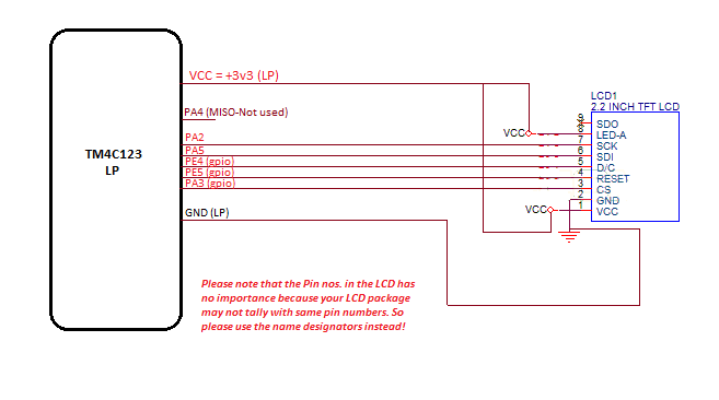
First the interconnections:

This LCD comes with a SPI connection header along with some extra control pins. Mine was a 2.2" LCD, but yours may be different and will work as long as controller and important parameters remains the same. I did not use the parallel connection, so have no clue.

TFTLCD_2.2Demo.zip

Second is the initialization code:


Please take care that the code to be written first initializes the MCU ports and configures the SPI and GPIO fns. Then initializes the LCD as per the datasheet commands. The initialization function that I used for Tiva or MCU is given below. You have to ensure that the proper headers are included and the Tivawares used here are properly installed. Otherwise, errors will come during compilation of these functions. Also the project folder settings, path variables and other workspace related settings have to be good in your IDE. I have used CCS v6.0 here:

#include <stdint.h>

#include <stdbool.h>

#include "IFT_LCD_PenColor.h"

#include "IFT_LCD_font.h"

#include "IFTSPI2_2LCD.h"

#include "inc/hw_memmap.h"

#include "inc/hw_types.h"

#include "driverlib/rom.h"

#include "driverlib/rom_map.h"

#include "driverlib/sysctl.h"

#include "driverlib/gpio.h"

#include "driverlib/ssi.h"

#include "inc/hw_gpio.h"

#include "driverlib/pin_map.h"


void   TivaInit(void)

{

           SysCtlPeripheralEnable(SYSCTL_PERIPH_GPIOE); // PE4 = D/C' , PE5 = RESET

           SysCtlPeripheralEnable(SYSCTL_PERIPH_GPIOF); // LEDs for debugging only, not requierd in final

           SysCtlPeripheralEnable(SYSCTL_PERIPH_GPIOA);// SSI pins

           SysCtlDelay(SysCtlClockGet()/10);// 100mS delay

           SysCtlPeripheralEnable(SYSCTL_PERIPH_SSI0);


//         never_declared = 35qr;


           GPIOPinTypeGPIOOutput(GPIO_PORTF_BASE, LPLEDs);


/////////////////////OTHER CONTROL LINES////////////////////////////////////////////

           GPIOPinTypeGPIOOutput(GPIO_PORTA_BASE, CS);//

           GPIOPinTypeGPIOOutput(GPIO_PORTE_BASE, DC|RESET);


/////////////////SSI CONFIG HERE//////////////////////////////////////////////////////


           SSIDisable(SSI0_BASE); // disables th SSI module as required for init

              GPIOPinConfigure(GPIO_PA2_SSI0CLK);

              GPIOPinConfigure(GPIO_PA4_SSI0RX);

              GPIOPinConfigure(GPIO_PA5_SSI0TX);


              GPIOPinTypeSSI(GPIO_PORTA_BASE, GPIO_PIN_2 | GPIO_PIN_4|GPIO_PIN_5);


              SSIClockSourceSet(SSI0_BASE, SSI_CLOCK_SYSTEM); // sets the system clock as the source of clock


              SSIConfigSetExpClk(SSI0_BASE, SysCtlClockGet(), SSI_FRF_MOTO_MODE_2,SSI_MODE_MASTER, 20000000, 8);// defines base, System clk, Mode 0 = SPH = SPO = 0,Master, 20MHz, no. of bits = 8 = 1 byte transfer


              SSIEnable(SSI0_BASE); // enables SSI


////////////////////// SSI CONFIG ENDS/////////////////////////////////////////

}


Next is the function used for initialization of the LCD:

This fn. Will initialize the ILI9341 and will also clear the screen to a black screen. The constants used below are here as follows:

#define              AllPins                                                GPIO_PIN_0|GPIO_PIN_1|GPIO_PIN_2|GPIO_PIN_3|GPIO_PIN_4|GPIO_PIN_5|GPIO_PIN_6|GPIO_PIN_7

#define              TFTControlPins                                  GPIO_PIN_4|GPIO_PIN_5|GPIO_PIN_6|GPIO_PIN_7

#define              TFTReset                                        GPIO_PIN_4

#define              LPLEDs                                          GPIO_PIN_1|GPIO_PIN_2|GPIO_PIN_3

#define              u8                                                     unsigned char

#define              u16                                             unsigned int

#define              u32                                             unsigned long

#define              MSB                                                    GPIO_PORTB_BASE

#define              LSB                                                    GPIO_PORTD_BASE

// SSI RELATED DEFINITIONS, ONLY FOR 2.2" LCD //

#define              SCK                                                    GPIO_PIN_2//PORT A, SSI 0 ONLY

#define              CS                                                     GPIO_PIN_3

#define              MISO                                            GPIO_PIN_4

#define              MOSI                                            GPIO_PIN_5

#define              DC                                                     GPIO_PIN_4// PORT E

#define              RESET                                           GPIO_PIN_5// PORT E

//Pallete Colors in 16 bit values

#define WHITE               0xFFFF

#define BLACK               0x0000

#define BLUE                0x001F // 0000 0000 0001 1111

#define BRED             0XF81F

#define GRED                0XFFE0

#define GBLUE              0X07FF

#define RED                 0xF800 // 1111 1000 0000 0000

#define MAGENTA             0xF81F

#define GREEN               0x07E0 // 0000 0111 1110 0000

#define CYAN                0x7FFF

#define YELLOW              0xFFE0

#define BROWN                      0XBC40 //Brown

#define BRRED                      0XFC07 //Brownish red

#define GRAY                       0X8430 //Gray


And here is the initialization function:


void Lcd_Init(void)

{

       GPIOPinWrite(GPIO_PORTA_BASE, CS,CS);

    //TFT_RST=1;

       GPIOPinWrite(GPIO_PORTE_BASE, RESET,0x20);

    //delay_ms(5);

       SysCtlDelay(SysCtlClockGet()/2);// 5 ms delay

    //TFT_RST=0;

       GPIOPinWrite(GPIO_PORTE_BASE, RESET,0);

    //delay_ms(15);

       SysCtlDelay(SysCtlClockGet()/2);// 15 ms delay

    //TFT_RST=1;

       GPIOPinWrite(GPIO_PORTE_BASE, RESET,0x20);

    //delay_ms(15);

       SysCtlDelay(SysCtlClockGet()/2);// 15 ms delay

    //TFT_CS =0;

       GPIOPinWrite(GPIO_PORTA_BASE, CS,0x08);

       SysCtlDelay(SysCtlClockGet()/100);// 15 ms delay

       GPIOPinWrite(GPIO_PORTA_BASE, CS,0);


       LCD_WR_REG(0xCB);

    LCD_WR_DATA8_SSI(0x39);

    LCD_WR_DATA8_SSI(0x2C);

    LCD_WR_DATA8_SSI(0x00);

    LCD_WR_DATA8_SSI(0x34);

    LCD_WR_DATA8_SSI(0x02);


    LCD_WR_REG(0xCF);

    LCD_WR_DATA8_SSI(0x00);

    LCD_WR_DATA8_SSI(0XC1);

    LCD_WR_DATA8_SSI(0X30);


    LCD_WR_REG(0xE8);

    LCD_WR_DATA8_SSI(0x85);

    LCD_WR_DATA8_SSI(0x00);

    LCD_WR_DATA8_SSI(0x78);


    LCD_WR_REG(0xEA);

    LCD_WR_DATA8_SSI(0x00);

    LCD_WR_DATA8_SSI(0x00);


    LCD_WR_REG(0xED);

    LCD_WR_DATA8_SSI(0x64);

    LCD_WR_DATA8_SSI(0x03);

    LCD_WR_DATA8_SSI(0X12);

    LCD_WR_DATA8_SSI(0X81);


    LCD_WR_REG(0xF7);

    LCD_WR_DATA8_SSI(0x20);


    LCD_WR_REG(0xC0);    //Power control

    LCD_WR_DATA8_SSI(0x23);   //VRH[5:0]


    LCD_WR_REG(0xC1);    //Power control

    LCD_WR_DATA8_SSI(0x10);   //SAP[2:0];BT[3:0]


    LCD_WR_REG(0xC5);    //VCM control

    LCD_WR_DATA8_SSI(0x3e);

    LCD_WR_DATA8_SSI(0x28);


    LCD_WR_REG(0xC7);    //VCM control2

    LCD_WR_DATA8_SSI(0x86);  //--


    LCD_WR_REG(0x36);    // Memory Access Control

    LCD_WR_DATA8_SSI(0x48);


    LCD_WR_REG(0x3A);

    LCD_WR_DATA8_SSI(0x55);


    LCD_WR_REG(0xB1);

    LCD_WR_DATA8_SSI(0x00);

    LCD_WR_DATA8_SSI(0x18);


    LCD_WR_REG(0xB6);    // Display Function Control

    LCD_WR_DATA8_SSI(0x08);

    LCD_WR_DATA8_SSI(0x82);

    LCD_WR_DATA8_SSI(0x27);


    LCD_WR_REG(0xF2);    // 3Gamma Function Disable

    LCD_WR_DATA8_SSI(0x00);


    LCD_WR_REG(0x26);    //Gamma curve selected

    LCD_WR_DATA8_SSI(0x01);


    LCD_WR_REG(0xE0);    //Set Gamma

    LCD_WR_DATA8_SSI(0x0F);

    LCD_WR_DATA8_SSI(0x31);

    LCD_WR_DATA8_SSI(0x2B);

    LCD_WR_DATA8_SSI(0x0C);

    LCD_WR_DATA8_SSI(0x0E);

    LCD_WR_DATA8_SSI(0x08);

    LCD_WR_DATA8_SSI(0x4E);

    LCD_WR_DATA8_SSI(0xF1);

    LCD_WR_DATA8_SSI(0x37);

    LCD_WR_DATA8_SSI(0x07);

    LCD_WR_DATA8_SSI(0x10);

    LCD_WR_DATA8_SSI(0x03);

    LCD_WR_DATA8_SSI(0x0E);

    LCD_WR_DATA8_SSI(0x09);

    LCD_WR_DATA8_SSI(0x00);


    LCD_WR_REG(0XE1);    //Set Gamma

    LCD_WR_DATA8_SSI(0x00);

    LCD_WR_DATA8_SSI(0x0E);

    LCD_WR_DATA8_SSI(0x14);

    LCD_WR_DATA8_SSI(0x03);

    LCD_WR_DATA8_SSI(0x11);

    LCD_WR_DATA8_SSI(0x07);

    LCD_WR_DATA8_SSI(0x31);

    LCD_WR_DATA8_SSI(0xC1);

    LCD_WR_DATA8_SSI(0x48);

    LCD_WR_DATA8_SSI(0x08);

    LCD_WR_DATA8_SSI(0x0F);

    LCD_WR_DATA8_SSI(0x0C);

    LCD_WR_DATA8_SSI(0x31);

    LCD_WR_DATA8_SSI(0x36);

    LCD_WR_DATA8_SSI(0x0F);


    LCD_WR_REG(0x11);    //Exit Sleep

 //   delayms(120);

       SysCtlDelay(SysCtlClockGet()/2);// 200 ms delay


    LCD_WR_REG(0x29);    //Display on

    LCD_WR_REG(0x2c);


    SysCtlDelay(SysCtlClockGet()/10);


    LCD_Clear(BLACK);

       BACK_COLOR=BLUE;

       POINT_COLOR=WHITE;


}


However, if you want to view a screen in other colors, you can select other colours in the LCD_Clear function, e.g.: LCD_Clear(GREEN) or LCD_Clear(BLUE);

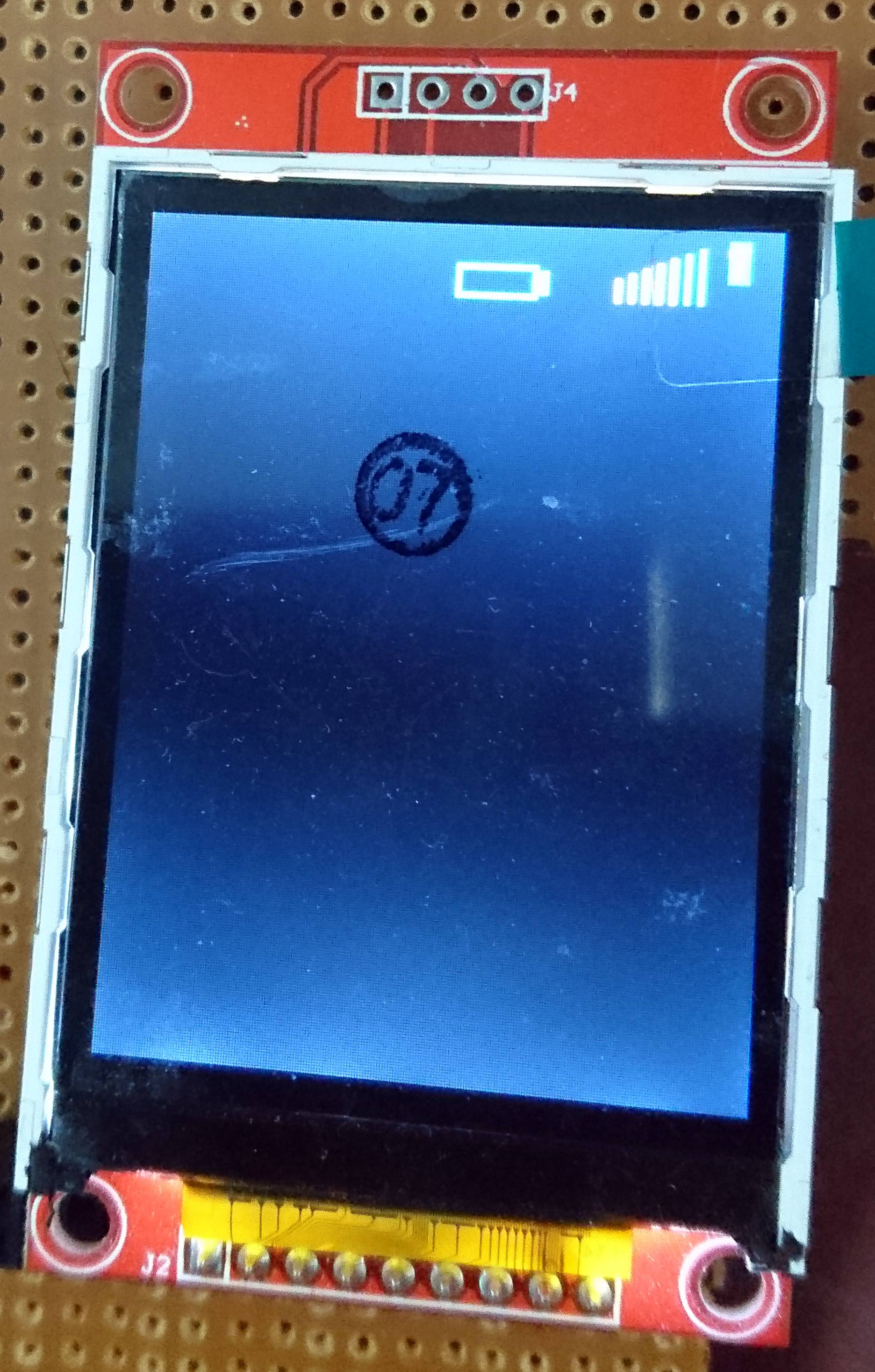
I have also included the export of the CCS project for your need. If you want, you can use the included functions like TFTFill, Draw rectangle, draw circle, etc to create your own simple GUI. Detailed explanation of the initialization codes are out of scope of this space. If needed I can explain. The included project will display a mobile tower bar and increment from 0% signal to 100% singal from white to green in colour. Also a charging battery symbol is there. AND SORRY AS THE CODE IS A BIT MESSED UP AS IT WAS MADE IN A HASTE. WORKING ON IT TO MAKE IT MORE STRUCTURED.


THANKS TO AMIT ASHARA, cb1, BP101, ROBERT ADSETT FOR HELPING ME RESOLVE MY CODE ISSUES!

  • Hello Turjasu

    We really appreciate your post on the panel code and acknowledgements to forum members

    Regards
    Amit
  • Indeed Amit,

    Turjasu - great job - terrific that you, "Stuck with this" and now enjoy the pleasure of success.

    And - you were thoughtful & kind enough to post your key code for others - and to thank helpers. (especially Amit)

    I even noted - and APPLAUD - your "special" care in describing the LCD by pin function (not number - which changes - as you warn) and by your foresight in alerting users to "first" initialize their MCU - before outputting to the Lcd.   Many may have missed - wasted time - but for your anticipation!  That's simply GREAT!
     
    Good luck - keep measuring & displaying...and {closing} your functions...

    BTW - I'm sure that (many) would appreciate your report of the duration required to "CLS."   (clear the screen)   SPI eases interface - yet cannot match parallel for display read/write/clear speed...   Might you comment?  Merci.


  • Yes. It would not have been possible without your help! Thanks again
  • Might you comment as to the time required to (fully) Clear your Screen under the SPI display interface?
  • Hello cb1

    Being a little more invasive: Is the grlib or a custom lib for drawing the image?

    Regards
    Amit
  • Hi Amit,

    I believe (much) of this stems from (another's) library.   (Jack Bresenham's work - cast in this presentation - telegraphs.)

    Strange that Turjasu has been so good @ listing & anticipating pitfalls - yet has repeatedly "shied" from CLS execution time. (my guess - can you say, "L O N G ?") and S L O W... SPI gives on one hand - extracts its "pound of flesh" from another. (in our world - unusable!)   Design "convenience" never/ever should trump performance - and that's what SPI has wrought!

    SPI or I2C (even) can be made to work - but only as the commo interface - with a high-performing, parallel connected (16 bit data, minimum) MCU "talking to the display in parallel."   This high-performing, display connected, MCU would receive - then process user data - and "machine gun" it out to the display.   And only (and always) via parallel...

  • The libraries, as i have said is not done by me. I have received them from the lcd maker, but i have converted them for use with ccs.
    I donot know what wrong i have done.
    About execution time, what are you asking about? Im sorry i could not get.
    I have just retried and arranged the whole thing with help from you people. Sorry for my mistakes, if any
    Im not an expert in this, still learning and sharing whatever i learn

    Regards,
    Turjasu Pyne


    ---- cb1- wrote ----


    A Message from the TI E2E™ Community
    Texas Instruments


    cb1- replied to Initializing ILI9341 based Color TFT with TM4C123 using SPI & GPIO.

    Hi Amit,

    I believe (much) of this stems from (another's) library. (Jack Bresenham's work - in this presentation - telegraphs.)

    Strange that Turjasu has been so good @ listing & anticipating pitfalls - yet has repeatedly "shied" from CLS execution time. (my guess - can you say, "L O N G ?") and S L O W... SPI gives on one hand - extracts its "pound of flesh" from another. (in our world - unusable!)


    You received this notification because you subscribed to the forum.  To unsubscribe from only this thread, go here.

    Flag this post as spam/abuse.

  • TURJASU PYNE1 said:
    About execution time, what are you asking about?

    You've nothing to, "be sorry about."  

    SPI has the advantage of easing the MCU - Display interface.   Yet that "easing" greatly increases the time to perform a (serious) display update.  (i.e. a display CLEAR, or replacement of one full-screen image w/another (full-screen) image.

    It is this, "Time to fully clear the display" and/or "Time to redraw a full-screen image" which has been requested.

    Cell phones & Tablets have placed Cortex M4 (and lesser) MCUs at grave disadvantage when comparing Display Quality and Display Update Rates!   Using SPI - rather than a wide parallel bus - further slows the display update rate - so much so that users (always) will note - and (generally) will NOT be pleased...  

    My goal was to "sound this SPI Alert" - so that "follow-on" readers here - (lured by quick/easy interconnect) will not be disappointed when "Tortoise Updates" result!   (compared to 16 bits (or beyond) parallel (aka: the hare!)

    Again - if you "fill your screen" then issue a, "Clear Entire Screen" command - approximately how long does that take?

  • Okay. I get it.
    Well for clearing the screen, the refresh rate is around 500ms. That is what i have seen.
    I have also used some dynamics in my screen like the battery charging indicator n stuffs, and i didnot notice any tearing effect or dragging effect.
    Well one thing is for sure. That is if anyone is using a video for display, then i donot know because with this kind of refresh rate, full screen re drawing is rather impossible and might affect the display field graphics.

    However, i have also seen that using spi was preferable because using 16 pins for data, and then again some more for gpio would render the tiva useless almost, because there would be hardly any pins available to interface other devices to the mcu.

    My recommendation is that, if any userz design is using this display in an existing system with other mcu over spi, then migration may be easy by porting this project to tm4c.
    Also using this display may be limited to occasions where full screen refresh updates with high refresh rate is rather not required, as this might not accomplish breathtaking results. Small devices with small dynamics and mostly static overview graphics is ideal for these display devices

    I am still working on development of small gui items using this controller and will surely provide them once done.

    Thanks cb1_mobile
  • Thank you - that (~500mS) is what (Amit) and I were after.   Such time-span indicates that a "CLS" command would be highly notable - perhaps (even) upon a "line-by-line" basis.

    Yet - just as you SO well stated - "small dynamics and/or (mostly) static graphics" is the (most practical) use for such MCU-Display "matings." 

    Unstated in your neat review was the (possible) use of a Cortex M4 (at the display & dedicated to display service) via far faster, wide parallel interface.   This (display) M4 would then receive & process "command/control & data packets" sent via a serial interface (perhaps a 2nd M4).

    This method achieves (far faster) display updates - yet maintains the convenience of a serial connection.   (albeit @ the cost of an added MCU)

  • Hello Turjasu,

    As cb1 stated, 500ms is too high. Is it the SSI clock rate and the panel size that limit it?

    Regards
    Amit
  • No. The ssi clock rate is quite fast. I hv set it at 20 mhz in the api ssiconfigsetexpclk() , but this is the rate at which the controller ili9341 is clearing the screen. It clears the screen once the command is dumped thru ssi alongwith the rgb bits value ( here blak).

    I hv tried many times to increase it, but this is the limit. 

    The 500 ms is the value i have measured approx. It may be somewhere between 350 ms to 500ms max.

    I will re try some more optimisations and get back on the same


  • Hello Turjasu,

    I think maths should be applied first to get the best case rate noting what steps are needed to display an image. Then based on the number of bytes to be sent for a pixel it may be calculated as below

    Best Case total time for full image display = (Number of Pixels * BPP)/SSI Clock Rate

    To optimize the display time select the region which needs the change, clear it and display it.

    Regards
    Amit
  • TURJASU PYNE1 said:
    this is the rate at which the controller ili9341 is clearing the screen.    It clears the screen once the command is dumped thru ssi 

    My small firm has used many such LCD/TFT Controllers - yet (I don't recall) this one.  

    My concern was - in absence of a dedicated, "Clear Screen Command" that you would have to perform (perhaps) 9600 * 2, individual, 8 bit SPI transfers, to fully "Clear the Screen."   In such case - or when drawing a completely new screen (i.e. one rich w/pixel data) you may have to "dump" all 19,200 SPI bytes to the screen.

    That takes time - and a 16 bit, parallel data transfer, would result in (at minimum) an order of magnitude improvement.

    BTW - I'd not characterize a single or few byte "Command Transmission" to a display as a "dump."  (dump usually reserved for a substantial amount of data being passed)

    Would you be so good as to clarify if ILI9341 employs a single (or few byte) command sequence to Clear the Screen?  (the alternative is to "write black", to each/every of your 9600 TFT pixels, and if 16 bit color was selected, such requires two SPI transfers per pixel...)  

    BTW (2) - you've been very good in responding and seeking to share your findings w/forum users.   Bravo - much appreciated...

  • Amit sir i will perform the test as per your calculations and get back to you asap.

    Cb1 sir, thanks. I understand your point. Im still very new to this one. Im still doimg RnD with the controller n the lcd. I have noted the points and will get back soon.

    Thanks again!

    Regards,
    Turjasu Pyne


    ---- cb1- wrote ----


    A Message from the TI E2E™ Community
    Texas Instruments


    cb1- replied to Initializing ILI9341 based Color TFT with TM4C123 using SPI & GPIO.

    TURJASU PYNE1
    this is the rate at which the controller ili9341 is clearing the screen.    It clears the screen once the command is dumped thru ssi 

    My small firm has used many such LCD/TFT Controllers - yet (I don't recall) this one.  

    My concern was - in absence of a dedicated, "Clear Screen Command" that you would have to perform (perhaps) 9600 * 2, individual, 8 bit SPI transfers, to fully "Clear the Screen."   In such case - or when drawing a completely new screen (i.e. one rich w/pixel data) you may have to "dump" all 19,200 SPI bytes to the screen.

    That takes time - and a 16 bit, parallel data transfer, would result in (at minimum) an order of magnitude improvement.

    BTW - I'd not characterize a single or few byte "Command Transmission" to a display as a "dump."  (dump usually reserved for a substantial amount of data being passed)

    Would you be so good as to clarify if ILI9341 employs a single (or few byte) command sequence to Clear the Screen?  (the alternative is to "write black, to each/every of your 9600 TFT pixels, and if 16 bit color was selected, such requires two SPI transfers per pixel...)  

    BTW (2) - you've been very good in responding and seeking to share your findings w/forum users.   Bravo - much appreciated...


    You received this notification because you subscribed to the forum.  To unsubscribe from only this thread, go here.

    Flag this post as spam/abuse.

  • TURJASU PYNE1 said:
    Im still doimg RnD with the controller n the lcd

    Thanks your (once again) rapid & caring response.

    My small tech firm works at the nexus (intersection) of Tech, Law & Investment.   As such - we have become (very) much aware of what constitutes, "Research."   In most all countries - taxing authorities produce & provide strict definitions of "just what" qualifies as, "Research."  

    Research "sounds nice" but in most cases these taxing authorities wish to greatly limit those activities which "qualify" as legitimate, "Research."   From what you've described (and as good as your development work has been) my sense is that your work more properly should be classed as, "D n D" (Design and Development!)   That's what our certified accountants entered upon our tax returns - even when (and especially when) our past tech firm did well enough to, "Go Public!"

    Governments encourage "Research" and provide substantial tax credits for work which "fully meets" their "Research" definitions.   Usually - but not always - "Research classification" is limited to those firms which:

    • employ highly specialized, often very expensive technical equipment
    • employ a substantial number of PhD's with specialties very well matching the "Research"
    • are able to provide critical documentation to substantiate the time, accomplishments, and critical nature of such "Research."

    Our tech efforts - though generating consistent Sales growth & Operating profits - cannot meet the necessary taxing authority requirements to secure, "Research Tax Treatment" (i.e. Deductions). 

    Design and Development (always) is far better received (if and when) you seek investors.   Most "Venture Capitalists" will reject those (most often, small) firms describing their efforts as "Research" - even if the development is otherwise - quite good.

    So "Big Deal" - why has cb1 gone "off on this tangent?"   Many times we've seen small firms (mistakenly), "believe" (I.e. hope) that their efforts qualified as, "Research."   And they then, "Spent funds they did not (really) have - counting upon the "Research Deductions."   And - when the taxing authority (IRS w/in USA) denied those (unqualified) "Research" deductions - monumental pain/suffering resulted!    My attempt here is to better acquaint forum members w/some aspects of tech-legal dealings - and "steer them from hostile ports."

    Schools - almost universally (and around the globe) mistakenly assign students, "Research" projects.   And the (real) Researchers (properly) resent the over (and incorrect) word usage.   Such students & engineers are "Investigators" - 20 minutes of youtube viewing (while multi-tasking) does not (quite) a "Researcher" make!

    As always - every situation proves unique/different - and each individual or firm must engage qualified (legal & financial) expertise to avoid unpleasantness.   As a general rule - avoid use of "Research" - recall that a small firm "went public" operating only under, "Design and Development."

  • The calculation here it goes:

    Number of pixels = 240 x 320 = 76800
    BPP = 16 bits here
    SSI Clock Rate = 20MHz

    so Best Case total time for full image display = (76800 x 16)/20000000 = 0.06144 or 61.4 mS

    But the point is that the function that sends the 16 bits of pixel data actually sends it in to cycles as the SPI mode is 8 bit mode. So will that again affect or double the time to around 150 mS ?

    Please let me know if i have gone wrong
  • Thanks cb1 for sharing your information.
    Indeed I quite agree with your point on DnD! thats wat we have been doing really and not much of this has gone into the resource for reserch. My firm, I being one of the owners, have been concentrating on the development on embedded apps using MCU in specific sectors like defense, home automation, SSI and Micro SI etc, where more of the efforts go into the term called DnD indeed.
    However, since i belong to india, here the present govt. is supporting growing and small organizations to take up challenging works and setup new firms called more suitably as entrepreneurial setups. And Im happy in that line :)
    Our taxation and legal routines do better acknowledge the DnD more and more correctly pointed out in the terms of taking up matters with some investors in our job and products / topics of encouragement, DnD will be here to take up more of a time and support .

    however, its never "off the tangent" and guidances from seniors like you are very important for minute startups like mine. So I'm so thankful for your sharing and concern. thanks sir
  • Generally that's correct (your calculation) - but don't you assume that each/every SPI transmission proceeds w/out delay!    And - in fact - aren't you required to "restore CS" for some minimum time period - prior to (each/every) SPI transfer?   And - if that's true - that calculation has "escaped" your formula.

    Now your TM4C can transfer 16 bits in one go - would not that eliminate one-half of those "SPI transfer" delays?   (and you've noted there are 76.8K of those delays!)

    My small tech group has "yet to see"  - an SPI-based TFT/LCD Controller - able to "break" 250mS when performing an "entire screen" clear or redraw.   (assumes that an automated CLS (clear) has not been implemented)

    As you so well noted earlier - for applications NOT requiring dynamic screen updates/redraws - dramatically slowed screen draws (may) be accepted.   Rapid cycling between widely different appearing screens (so much the "norm" today via cells & tablets) - is your enemy and "must" be minimized (i.e. avoided) at all costs...  (and hard to do...)

    *** just saw your answering post (DnD vs RnD).   Many outstanding firms in India perform fully qualified RnD.   My goal was to alert you/others to the (potential) for harmful financial outcomes - should the taxing authorities deem your efforts (not quite) to their standards (and you've counted {heavily} upon hoped for deductions/tax treatment!!)  

    Again - often only local professionals - well versed in (current) tax law and accounting - are suitably equipped to make such key/critical judgements.    May I urge you/others to, "Save money by other means" and "engage the best qualified tax/legal professionals sooner" - rather than later...   (Awareness - feeding Risk-Reward analysis - must be well (and regularly) - attended!)