


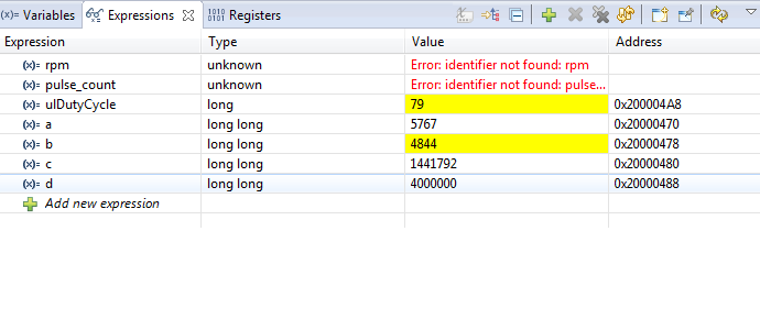
Hi, i trying to make a simple code to understand more about PWM. Basically, when i press SW1 or SW2, the duty circle change and the brightness of red led change. But when i read the clock of PWM, system and period, the result isn't like i expected
the PWMclock not equa to sysclock/16 = 4mhz/16 = 250000, can some one explain why i got the pwmclock result like that, did i understand any thing wrong?.

Sorry because my crappy english.
Thanks

#include <stdint.h>
#include <stdbool.h>
#include <math.h>
#include <time.h>
#include "inc/hw_types.h"
#include "inc/hw_memmap.h"
#include "driverlib/adc.h"
#include "inc/tm4c123gh6pm.h"
#include "inc/hw_ssi.h"
#include "driverlib/gpio.h"
#include "driverlib/fpu.h"
#include "driverlib/hibernate.h"
#include "driverlib/interrupt.h"
#include "driverlib/pin_map.h"
#include "driverlib/rom.h"
#include "driverlib/sysctl.h"
#include "driverlib/systick.h"
#include "driverlib/uart.h"
#include "driverlib/timer.h"
#include "driverlib/ssi.h"
#include "inc/hw_ints.h"
#include "driverlib/pwm.h"
#include "inc/hw_gpio.h"

void ButtonISR(void);

long ulDutyCycle=50;//Duty cycle of PWM
long ulPeriod;//Period of PWM
int read;
int64_t a,b,c,d;

#define LED_RED		GPIO_PIN_1
#define LED_BLUE	GPIO_PIN_2
#define LED_GREEN	GPIO_PIN_3
#define SW1			GPIO_PIN_4
#define SW2 		GPIO_PIN_0

void ButtonISR()
{
	GPIOIntClear(GPIO_PORTF_BASE, SW1|SW2);
	PWMGenDisable(PWM1_BASE, PWM_GEN_2);

	GPIOPinWrite(GPIO_PORTF_BASE,LED_GREEN|LED_BLUE, LED_GREEN|LED_BLUE);
	a = PWMGenPeriodGet(PWM1_BASE, PWM_GEN_2);
	b = PWMPulseWidthGet(PWM1_BASE, PWM_OUT_5);
	c = SysCtlPWMClockGet();
	d = SysCtlClockGet();
	read=GPIOPinRead(GPIO_PORTF_BASE,SW1|SW2);
	if((read&SW1 )==0)
	{
		ulDutyCycle = ulDutyCycle+5;
	}
	else if((read&SW2)==0)
	{
		ulDutyCycle = ulDutyCycle-5;
	}

	if(ulDutyCycle>=100)
	{
		ulDutyCycle=99;
	}
	else if(ulDutyCycle<=0)
	{
		ulDutyCycle=1;
	}
	//GPIOPinWrite(GPIO_PORTF_BASE,LED_GREEN|LED_BLUE, 0);
	PWMPulseWidthSet(PWM1_BASE, PWM_OUT_5,ulPeriod*ulDutyCycle/100);
	PWMGenEnable(PWM1_BASE, PWM_GEN_2);
}

void main(void) {
	SysCtlClockSet(SYSCTL_SYSDIV_50|SYSCTL_USE_PLL|SYSCTL_OSC_MAIN|SYSCTL_XTAL_16MHZ); // sys clock  = 4mhz
	SysCtlPWMClockSet(SYSCTL_PWMDIV_16);  // pwm clock = 4mhz/16 = 250khz

	SysCtlPeripheralEnable(SYSCTL_PERIPH_GPIOF);
	//Config GPIO that connect to LED - PIN 2,3
	//GPIOPinTypeGPIOOutput(GPIO_PORTF_BASE,GPIO_PIN_2|GPIO_PIN_3);
	//Turn LEDs
	//GPIOPinWrite(GPIO_PORTF_BASE,LED_GREEN|LED_BLUE, LED_GREEN|LED_BLUE);
	//Config Buttons
	HWREG(GPIO_PORTF_BASE + GPIO_O_LOCK) = GPIO_LOCK_KEY;
	HWREG(GPIO_PORTF_BASE + GPIO_O_CR) |= 0x01;
	HWREG(GPIO_PORTF_BASE + GPIO_O_LOCK) = 0;

	GPIODirModeSet(GPIO_PORTF_BASE,  SW1|SW2, GPIO_DIR_MODE_IN);
	GPIOPadConfigSet(GPIO_PORTF_BASE, SW1|SW2, GPIO_STRENGTH_2MA, GPIO_PIN_TYPE_STD_WPU);

	GPIOIntTypeSet(GPIO_PORTF_BASE,SW1|SW2, GPIO_FALLING_EDGE);
	GPIOIntRegister(GPIO_PORTF_BASE,&ButtonISR);
	GPIOIntEnable(GPIO_PORTF_BASE,SW1|SW2);
	IntEnable(INT_GPIOF);

	IntMasterEnable();
	//Enable the peripherals used by this program.
	SysCtlPeripheralEnable(SYSCTL_PERIPH_PWM1);//
	SysCtlPeripheralEnable(SYSCTL_PERIPH_GPIOF);
	ulPeriod = (SysCtlPWMClockGet()/250); //

	//Configure PF1 pins as PWM
	GPIOPinTypePWM(GPIO_PORTF_BASE, GPIO_PIN_1);
	GPIOPinConfigure(GPIO_PF1_M1PWM5);


	//Configure PWM Options
	PWMGenConfigure(PWM1_BASE, PWM_GEN_2, PWM_GEN_MODE_DOWN);
	PWMGenPeriodSet(PWM1_BASE, PWM_GEN_2, ulPeriod); // 1s

	PWMPulseWidthSet(PWM1_BASE, PWM_OUT_5, ulPeriod*ulDutyCycle/100);

	//Turn on the Output pins
	PWMOutputState(PWM1_BASE, PWM_OUT_5_BIT, true);

	//Enable the PWM generator
	//PWMGenEnable(PWM1_BASE, PWM_GEN_2);

	while(1)
	{

	}

}

