This thread has been locked.

If you have a related question, please click the "Ask a related question" button in the top right corner. The newly created question will be automatically linked to this question.

TMS570 MCU lockup state requiring a >210mS logic hing on the nRST pin to boot

Hello Ti team,

We’ve got a strange lockup issue with the TMS570LS21216SPGE that we need some help with please.

The symptom: Once in this error state the CPU doesn’t boot unless it is given a logic high (3V3) on the nRST pin for greater than 210mS. We unfortunately have no way of determining when the CPU gets into this error state because it doesn’t lockup while in the running state but only after a reboot.

Other related information:

  • We’ve got a windowed watchdog which has a 12mS high and a 170mS low pulse if it is not kicked in a 1-2mS window.

What we think is making it happen:

  • Reading of the flexray output buffer (OBF) when it exactly coincides with an incoming frame which is being written into the flexray message RAM by the flexrayCC. The read and write have to happen at the same time and on the same buffer(slot)

Flexray configuration

  • Only Channel-A is configured and used at 1 1mS gdCycle. Channel-B is not connected.

  • The flexray message buffer is configured for 17 static slots. Each slot is 44 bytes in length

  • No dynatic slots used.

Q1) Is this a known issue?

Q2) What is the minimum time required on the nRST pin to reset the CPU? Is the 210mS that we’re seeing a time required for this specific issue or is 210mS the minimum time for a logic high on the nRST pin to boot the chip?

Thanks, 


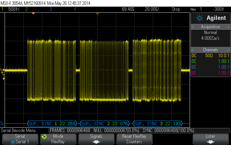
Attached image: flexray bus data.png shows a capture of the flexray bus with 3 nodes.


  • Correction to a few typos in the previous message:
    - CPU used is a TMS570LS20216SPGE
    - Flexray gdCycle is 1mS wide and not 11mS
    - In our setup the output of the watchdog is connected to the nRST pin of the CPU
  • Hi Jude,

    Q1: The issue you describe is not a known issue that I am aware of

    Q2: nRST needs to be asserted for a minimum of 150ns to insure the reset is seen by the system. However, if it is released just after the maxglitch filter time of 150ns, there is a possibility that reset will not be completely propagated across the entire device. As a result, I generally recommend asserting the nRST pin for a minimum of 1ms or greater. Given the timing of your WD, I don't believe there would be any issues with a proper reset of the device.

    With that said, nRST is a soft reset where the CPU is reset along with peripherals and various other parts of the chip. However, it is not a full reset meaning there could be parts of the device that remain unchanged from prior to nRST assertion. At this point, I don't know for sure if the Flexray state machine is one of those areas that is not necessarily reset and what you are seeing is a residual of the arbitration of the output buffer read vs the incoming packet.

    Can you provide additional details such as the reliable the recreation of the issue is and if possible, sample code that demonstrates the lockup issue?

    Also, when measuring the >210ms reset period, I interpret from your description this is measured on the nRST pin when the WD asserts the reset?

    Finally, I am also going to copy our Flexray expert so they can review your comments about the lock up scenario and provide additional input.
  • Hello Chuck,

    Sorry for not replying earlier. We were trying a few things out here after we initially heard from you and found the issue in our initialisation code and fixed it.

    Thanks for the support. This ticket can be closed.
  • Hi Jude,

    Terrific! I am glad you were able to resolve the issue. Please post again if anything else comes up for which you need support.