This thread has been locked.

If you have a related question, please click the "Ask a related question" button in the top right corner. The newly created question will be automatically linked to this question.

LM Flash programmer error ERROR**: Programming error 0x1

Other Parts Discussed in Thread: TM4C123GH6PZ, LMFLASHPROGRAMMER, UNIFLASH

Hi,

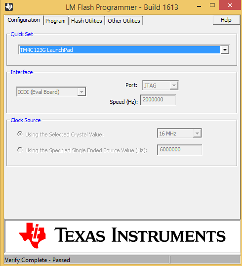
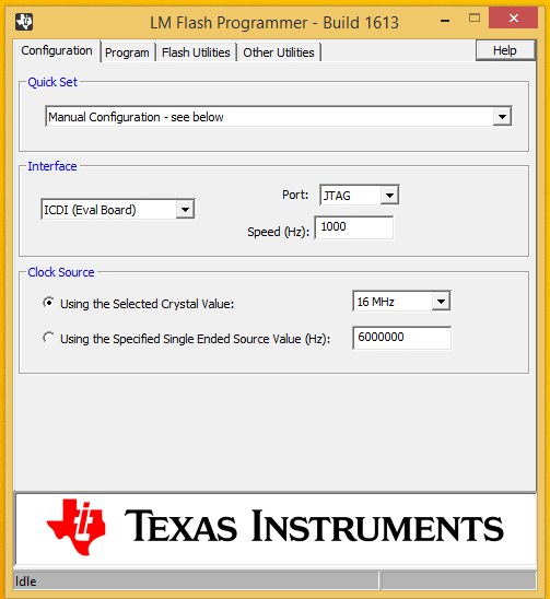
      I am using LM Flash programmer to burn the .bin file into TM4C123GH6PZ micro controller. I am using CCS 6.0.1, and when I will download this code to uC then it will run successfully but when I use LM Flash programmer then It will generate error randomly e.g. if I download a bin file 10 times it will successful but at 11th it will generate an error like "ERROR**: Programming error 0x1."  then even if I will not change hardware setting at the 12th attempt it will be successful so I am confuse where I am wrong? 

  • Hello Girish,

    The LMFlashProgrammer requires an ICDI device to download the bin image. What are you using to emulate the same?

    Regards
    Amit
  • I am using Tiva C Series LaunchPad device which is having ICDI interface, using this I can program my controller successfully but it generates error randomly as i mentioned in my previous post. e.g 10 times it won't give an error but at 11th attempt it generates an error ( i.e. ERROR**: Programming error 0x1) but without changing any connection if i click program button then it will be successful, but again at suppose 15th attempt it will generate an error, so my question is if I am doing something wrong e.g in connection or selecting speed or anything then why it will successfully program 10 times ?  and after an error even if i am not changing anything it will successful again for few attempts. And I am not able to understand the root cause of this unpredictable behavior.


  • Hello Girish

    So you must be running free wires between the boards?

    1. Make sure there is a good GND connection
    2. Also make sure that there is a good Pull Up since free wires are more sensitive to signal interference due to cross talk.
    3. Always a good idea to have a dedicated programmer.,

    Regards
    Amit
  • Dear Amit,

                  I don't have any free wire running and proper GND connection as well. I found one link where they said that these are occur because of OS problem e.g insufficient RAM etc. I am providing that link as follows

                http://www.msnx.net/

                            But they charge to solve the problem, Is there analysis is correct? Is this happening due due slow RAM. I checked it on two PCs one is fast windows 8.1  GB RAM 64 bit and another machine is windows xp Professional V2002 SP3 Celeron m CPU 440 freq - 1.86Ghz RAM 504MB. My requirement is that it should work on both so I can't ignore problem with slow one. So please suggest a proper solution.

  • Hello Girish,

    What perplexes me is how then is ICDI connected to your custom board if there are no wires between the LPad and your custom board? Please describe the connection.

    Regards
    Amit
  • Hello Amit,

                    You misunderstood me, of course I am using wired connection but i wanted to say that I am taking care to keep away any extra unnecessary wires as it may interfere in my operation. I am sending you my setup image so you will understand it how I am connecting my ICDI to Laptop. I am providing Power to micro controller via Power supply, USB cable from ICDI to Laptop and connect ICDI to micro controller board.

                     Is this problem really related to Windows OS and due to multiple operations running, less RAM etc...because I am facing more problem when I am using less configuration machine and when I close all background operations then chances of errors will become less. Kindly go through the following image of Setup for programming.

  • Here I am providing image where my programming process stuck up always, interestingly it stuck up mostly at 48% or sometime 0%.

    Also another important thing which I noticed is when I try to erase and blank checked for this it will never give me an error but if I am

    trying to program then it gives me 0x1 error. so one thing is clear that my set up connections are correct.

                         And when I program it using CCS then it will never generate an error but for the same kit or controller board when I use

    LM Flash programmer then it produce this 0x1 error.

  • Hello Girish,

    There are multiple places during programming where you may get the error code 0x1. As far as I could understand the code, the error is primarily when a check fails during the programming phase.

    1. Did you try to reduce the JTAG clock frequency?
    2. Do you have sufficiently strong pull up on the JTAG lines for your custom board?

    Regards
    Amit
  • Hi Amit,

              I tried by reducing JTAG Speed from default high value to even 1000 but it didn't solve my problem. when I do erase and Blank check option in Flash Utilities then while erasing flash and blank checking it never gives me an error, not even a single time but why it generates an error while programming ?

               On the other threads of Ti i read the same problem discussion where I read that this problem is related to system clock so use UNLOCK option in Debug Port UNLOCK, but I am not able understand this process, means how to do UNLOCK?..And what UNLOCK will do actually?

  • Hello Girish,

    If the Erase and Blank check work all the time, the issue may not be running the UNLOCK sequence. UNLOCK sequence is a method to mass erase the device when the JTAG port is disabled or a code has caused an operation that prevents the debugger from functionally attaching to the device.

    Can you please describe the code you have on the micro, e.g. what is the function and parameters being used for setting the system clock. More details on the thread below.

    e2e.ti.com/.../374640

    Can you also please paste a logical connection (since the picture does not show which pin from LaunchPad is connected to JTAG on the custom board)

    Regards
    Amit
  • Dear Amit,

                Sorry for late reply, As per your demand I am providing you my JTAG circuit connection and providing a code used for setting the system clock. Please go through it.

    Here is the JTAG circuit connection 

    And at micro controller pins

    And here is the code used for JTAG

    void main(void) {

           // Set the clocking to run directly from the crystal.

           SysCtlClockSet(SYSCTL_SYSDIV_2_5 | SYSCTL_USE_PLL | SYSCTL_XTAL_16MHZ |    SYSCTL_OSC_MAIN);

            SysCtlPeripheralEnable(SYSCTL_PERIPH_GPIOG);

           SysCtlPeripheralEnable(SYSCTL_PERIPH_GPIOC);

            //---------------------------------------------------------------

           //configure JTAG pins

           //---------------------------------------------------------------GPIOPinConfigure(GPIO_PC0_TCK);                                 //JTAG TCK

    GPIOPadConfigSet(GPIO_PORTC_BASE,GPIO_PIN_0,GPIO_STRENGTH_2MA,GPIO_PIN_TYPE_STD_WPU);

    GPIOPinConfigure(GPIO_PC1_TMS);                                    //JTAG TMS

    GPIOPadConfigSet(GPIO_PORTC_BASE,GPIO_PIN_1,GPIO_STRENGTH_2MA,GPIO_PIN_TYPE_STD_WPU);

    GPIOPinConfigure(GPIO_PC2_TDI);                                    //JTAG TDI

    GPIOPadConfigSet(GPIO_PORTC_BASE,GPIO_PIN_2,GPIO_STRENGTH_2MA,GPIO_PIN_TYPE_STD_WPU);

    GPIOPinConfigure(GPIO_PC3_TDO);                                    //JTAG TDO

    GPIOPadConfigSet(GPIO_PORTC_BASE,GPIO_PIN_3,GPIO_STRENGTH_2MA,GPIO_PIN_TYPE_STD_WPU);

    Please Correct me if I am doing something wrong.

  • Dear Amit, Sorry for late reply, As per your demand I am providing you my JTAG circuit connection and providing a code used for setting the system clock. Please go through it.

    Here is the JTAG Connection

    At the Micro controller Pins

    And For the code to set the system clock please go through the following code

    void main(void) {

                   // Set the clocking to run directly from the crystal.

           SysCtlClockSet(SYSCTL_SYSDIV_2_5 | SYSCTL_USE_PLL | SYSCTL_XTAL_16MHZ |    SYSCTL_OSC_MAIN);

            SysCtlPeripheralEnable(SYSCTL_PERIPH_GPIOG);

           SysCtlPeripheralEnable(SYSCTL_PERIPH_GPIOC);

           //configure JTAG pins

     GPIOPinConfigure(GPIO_PC0_TCK);                                 //JTAG TCK

    GPIOPadConfigSet(GPIO_PORTC_BASE,GPIO_PIN_0,GPIO_STRENGTH_2MA,GPIO_PIN_TYPE_STD_WPU);

    GPIOPinConfigure(GPIO_PC1_TMS);                                    //JTAG TMS

    GPIOPadConfigSet(GPIO_PORTC_BASE,GPIO_PIN_1,GPIO_STRENGTH_2MA,GPIO_PIN_TYPE_STD_WPU);

    GPIOPinConfigure(GPIO_PC2_TDI);                                    //JTAG TDI

    GPIOPadConfigSet(GPIO_PORTC_BASE,GPIO_PIN_2,GPIO_STRENGTH_2MA,GPIO_PIN_TYPE_STD_WPU);

    GPIOPinConfigure(GPIO_PC3_TDO);                                    //JTAG TDO

    GPIOPadConfigSet(GPIO_PORTC_BASE,GPIO_PIN_3,GPIO_STRENGTH_2MA,GPIO_PIN_TYPE_STD_WPU);

  • Hello Girish

    GPIO Port C for JTAG does not need a setup. Please note that JTAG is default by functionality. Please remove the code for Port C configuration.

    Regards
    Amit
  • Hello Amit,

                 I tried it by removing those line from code also I tied TCK and TMS pins to +3.3Volt through 10K Ohm Pull Up resistors, but still I am facing the same problem of Error 0x1. also I tried by reducing the speed upto 1000 but no effect.

    Here is the image for Pull Up modification

    Here is the image which shows my LM configuration

    I have commented following lines as per your suggestion,

    //configure JTAG pins

    /*GPIOPinConfigure(GPIO_PC0_TCK);                         //JTAG TCK
        GPIOPadConfigSet(GPIO_PORTC_BASE,GPIO_PIN_0,GPIO_STRENGTH_2MA,GPIO_PIN_TYPE_STD_WPU);
        GPIOPinConfigure(GPIO_PC1_TMS);                         //JTAG TMS
        GPIOPadConfigSet(GPIO_PORTC_BASE,GPIO_PIN_1,GPIO_STRENGTH_2MA,GPIO_PIN_TYPE_STD_WPU);
        GPIOPinConfigure(GPIO_PC2_TDI);                         //JTAG TDI
        GPIOPadConfigSet(GPIO_PORTC_BASE,GPIO_PIN_2,GPIO_STRENGTH_2MA,GPIO_PIN_TYPE_STD_WPU);
        GPIOPinConfigure(GPIO_PC3_TDO);                         //JTAG TDO
        GPIOPadConfigSet(GPIO_PORTC_BASE,GPIO_PIN_3,GPIO_STRENGTH_2MA,GPIO_PIN_TYPE_STD_WPU);
      */

    Should I do something else, Please Suggest.


  • Hello Girish,

    Is Pin 5 on the connector GND (symbols says so) or 3V3 as the name says so?

    Considering the issues, I would suggest using a XDS debugger with a mating header to match the 5 pin relimate as a more stable and long run solution.

    Regards
    Amit
  • Hi,

    Also the ICDI speed is too low (1000) - do not set it below 100000; 1,000,000 would be OK.

  • Hello Amit,

                PIN Number 5 is Ground PIN, and please try to reach to root cause of this issue as it is not possible for me to switch to another debugger. And I am curious to know why this is happening ? Kindly Reply

  • Hello Petrei ,
    I tried by reducing the speed, as I was expecting that at least on low speed it will work that's why I reduced it to this low level. But as per your suggestion I set it to 100000; OR 1,000,000 but still problem not resolved. Please suggest expert solution.
  • Hi,

    Two suggestions:

    1. Do start your LMFlash programming by pressing the reset button (if you have such on your board) or add temporarily such button. There is a difference in CCS/LMFlash behavior - while CCS make an software reset, seems LMFlash does not, so use a reset button. Same behavior on other tools, like OpenOCD.
    2. Keep in mind the minimum RAM requirement on your PC - recommended is 2G(XPsp3) - we noticed similar behavior on computers with less RAM than specified, and also in some cases, before HD to fail forever.

  • We note that you've (saved) the cost & effort of pulling-up "TDI." In light of your dedication to identifying causal nexus - can that (ever) be wise?

    Petrei's (always reset) advice is "dead-on" - our firm uses (only) IAR & J-Link - never/ever encounter your issue!   (J-Link insures reset)

    Note that the "ICDI" capability is a "bonus" w/LPad - it was not intended as "bullet-proof, uber-pro" device.   (surely you know that.)

    No one has yet to mention the "solidness" of your "board to board" connections. Are all crimps correct - do the headers mate perfectly with wire receptacles or have all interconnect solder joints been exhaustively viewed & tested?

    And - your code reviews a very mistaken (earlier) approach to JTAG. It is entirely possible that (other) programming "adventures" may have (somewhat) disturbed/impacted the ICDI MCU - rather than "pound" Amit (btw - he made no "demand" - he simply guided/suggested) use of a new/fresh LPad seems most reasonable...

  • Hello Girish,

    I do not have a physical board to work with, so any debug on my side is almost out of question, since I would need to connect a debugger to evaluate the JTAG transactions on the board.

    Regards
    Amit
  • Hello Amit & Petrei,
    The problem have been solved to great extend, Petrei your both suggestions worked for my problem 1) Set the speed to 100000 or 1,000,000 and 2) Do start your LMFlash programming by pressing the reset button.
    For others who will face this problem I am explaining steps you should do to solve this problem (expert says that the 0x1 Error occur in different environment but I am explaining solution by my own experience & Study on my custom board)....Steps are as follows,
    1. Reduce the speed & set it to 1,00,000 or 10,00,000
    2. Erase the flash before program using (Flash Utilities in LMFlash Programmer)
    3. Reset the board by pressing RESET Button
    4. And then click on Program button

    These steps solved my problem to great extent, not completely but now I am not getting that error repeatedly which was irritating one . Thanks a lot Amit & Petrei for your expert suggestions which helped me a lot to solve this problem. If you/anyone can suggest me the exact solution then I will be thankful to him.
  • Hi,
    Try also the Uniflash program. Better results than that you will not get, because as I said, this is due to the missing software reset inside tools (cb1 signaled also that other tools have that) .
  • Hello Petrei,

                Can you tell me the installation procedure of Uniflash? I tried to install but couldn't succeed. I tried to search the steps for Uniflash installation but didn't find. If you can then please explain in short or provide a link. Thanks in advance.

  • Hi,

    Take care  there are two Uniflash versions - one is dedicated to CC32xx processors - supposing you downloaded the right one, the installation procedure is the same as for any other PC application.

  • Hello Petrei,
    Which Uniflash Should I download for TM4C123GH6PZ Controller. I am confuse with this CC32xx and Sitara processor. Should I download the Tool from this link? will it suitable for my controller? Please reply
  • Hi,
    I noticed one new point with this LM Flash programmer, If no other application is running (especially Internet browser) then it works fine but as soon as I open a browser window then It started showing me this error. What do you think, Is there any relation with this ? Kindly reply.
    Regards - Girish
  • Sorry I forgot to provide a link in my previous post, Please go through it
    www.ti.com/.../uniflash
  • Hi,

    I do not observed such (bad) behavior - may be also related to RAM amount of your computer. Try to use only one window, close other applications (why do you need browser while flashing?)

  • Thanks for Reply Petrei, No I don't need browser while flashing but this behavior I observed so I wanted to know whether there is any relation with it. Now I understood that the problem is mostly due to insufficient RAM of Computer. Thank you once again.