Other Parts Discussed in Thread: TM4C1231H6PM
I am having problems receiving data from ssi1 port on the TM4C1231H6PM. The data that I receive is zeros from SSIDataGet. The SSI1 ports are connected to AD7190 chip from Analog Device. I have successfully set up the AD7190 on the TM4C129. Now, I am trying to port the setup onto the TM4C1231H6PM.
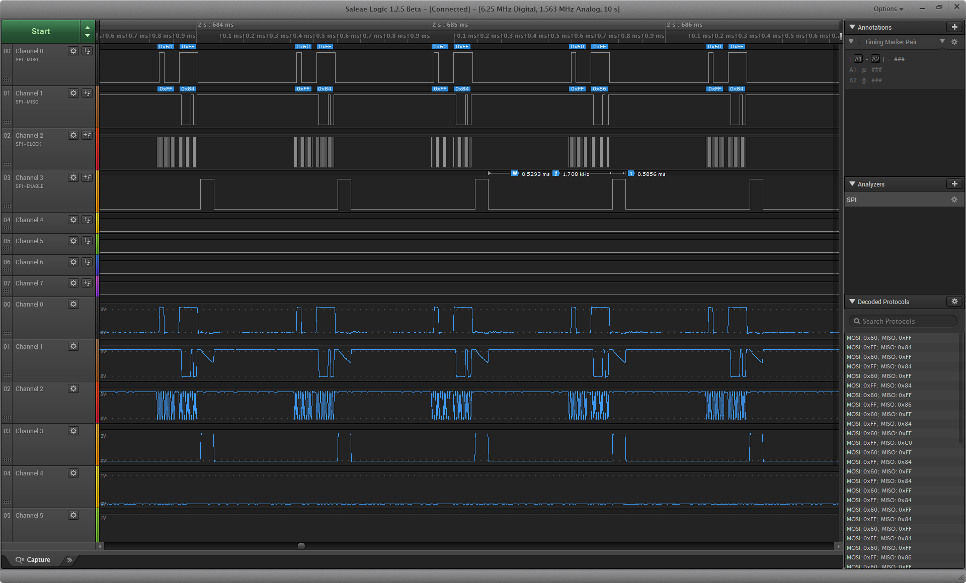
I think that I have set up the code ,correctly. I have posted the setup code below. The FSS is setup as an output pin. The function called ADC_ID should return the ID register value from the AD7190 chip but it returns zero. Next, I hooked up the SSI1 RX line to a logic analyzer and observed that I am receiving data from the AD7190.
Also, I have posted the functions SPI_BUS_Send and SPI_GET_DATA to show that I am managing the FIFO buffer with SSiDataPut and SSIDataGet.
I have been stuck on this problem for days and decided to finally post on to forum. Any suggestion or advice would be helpful.
Setup code:
void ADCInit(void);
void setup(void)
{
SysCtlPeripheralEnable(SYSCTL_PERIPH_GPIOA);
SysCtlPeripheralEnable(SYSCTL_PERIPH_GPIOB);
SysCtlPeripheralEnable(SYSCTL_PERIPH_GPIOD);
SysCtlPeripheralEnable(SYSCTL_PERIPH_GPIOF);
SysCtlPeripheralEnable(SYSCTL_PERIPH_UART1);
// SysCtlPeripheralEnable(SYSCTL_PERIPH_SSI0);
SysCtlPeripheralEnable(SYSCTL_PERIPH_SSI1);
SysCtlPeripheralEnable(SYSCTL_PERIPH_EEPROM0);// EEPROM
GPIOPinTypeGPIOOutput(GPIO_PORTF_BASE, GPIO_PIN_3); //CPU_LED
GPIOPinTypeGPIOOutput(GPIO_PORTF_BASE, GPIO_PIN_4); //DEBUG_LED
//GPIOPinTypeGPIOOutput(GPIO_PORTA_BASE, GPIO_PIN_3); // ADC1CS FSS
GPIOPinTypeGPIOOutput(GPIO_PORTD_BASE, GPIO_PIN_1); // ADC2CS FSS
// RS232_Uart
GPIOPinConfigure(GPIO_PB0_U1RX);
GPIOPinConfigure(GPIO_PB1_U1TX);
GPIOPinTypeUART(GPIO_PORTB_BASE, GPIO_PIN_0 | GPIO_PIN_1);
UARTClockSourceSet(UART1_BASE, UART_CLOCK_PIOSC);
UARTConfig(1, 115200, 16000000); // custom Uart function
UARTIntEnable(UART1_BASE, UART_INT_RX | UART_INT_RT);
IntEnable(INT_UART1);
SysCtlClockSet (SYSCTL_SYSDIV_1 | SYSCTL_USE_OSC | SYSCTL_OSC_MAIN | SYSCTL_XTAL_16MHZ);
// ADC Setup
ADCInit();
IntMasterEnable();
}
void ADCInit(void)
{
SSIDisable(SSI1_BASE); //ADC2
GPIOPinConfigure(GPIO_PD0_SSI1CLK);
GPIOPinConfigure(GPIO_PD2_SSI1RX);
GPIOPinConfigure(GPIO_PD3_SSI1TX);
GPIOPinTypeSSI(GPIO_PORTD_BASE, GPIO_PIN_0| GPIO_PIN_2 | GPIO_PIN_3);
SSIClockSourceSet(SSI1_BASE, SSI_CLOCK_SYSTEM); // sets the system clock as the source of clock
SSIConfigSetExpClk(SSI1_BASE, SysCtlClockGet(), SSI_FRF_MOTO_MODE_3, SSI_MODE_MASTER, 100000, 8);
SSIEnable(SSI1_BASE);
}
void ADC_ID(uint8_t ADCCS) // ADCCS = ADC2CS (GPIO_PORTD_BASE, GPIO_PIN_1)
{
uint8_t j=0;
uint32_t ID=0;
while( ( (ID & 0x0F) != 0x04 ) && j<25 )
{
ID=0;
// Continually poll the id register of the ADC and see what we get
GPIO_write( ADCCS, GPIO_LOW); //
//Make sure there is data before reading
SPI_BUS_Send( ADCCS,ID_Register ); // ID_Register == 0x60 sent to AD7190 .
ID = SPI_GET_DATA();
GPIO_write( ADCCS, GPIO_HIGH);
j++;
UartPrintLineHelper(RS232_Uart,"ID= %i", ID // Custom UART function to print ID
// ID always returns zero
}
}
GPIO_write( ADCCS, GPIO_HIGH);
void
SPI_BUS_Send( uint32_t ui32SPISend )
{
uint32_t ui32SPIget;
SSIDataPut( SSI1_BASE, ui32SPISend );
SSIDataGet( SSI1_BASE, &ui32SPIget );
while( SSIBusy( SSI1_BASE )){}
}
uint32_t SPI_GET_DATA()
{
uint32_t ui32SPIget;
SSIDataPut( SSI1_BASE , 0xFF ); // Dummy byte
SSIDataGet( SSI1_BASE , &ui32SPIget );
while ( SSIBusy( SSI1_BASE )){}
return ui32SPIget;
}