This thread has been locked.

If you have a related question, please click the "Ask a related question" button in the top right corner. The newly created question will be automatically linked to this question.

Brushless Positioning Control using tm4c123 tiva

Other Parts Discussed in Thread: TM4C123GH6PM, MOTORWARE, DRV8305, LM3S8971

I'm working on my Senior Project. It is a Brushless Gimbal System, like this one in youtube:

Brushless Gimbal examples: https://www.youtube.com/watch?v=qOuMNiSc8Qw

Actually, the big challenge is just to do a rotor positioning control of a brushless DC motor where the orientation angle is measured by a IMU sensor. The motor I am using is the EMAX CF2822. Here is a video of someone driving one CF2822:

EMAX CF 2822 - Position Control of a Brushless DC motor https://www.youtube.com/watch?v=tAXfprfT-rE

I have been working in this project for about 6 months. Now I have the motor driver (I.C. L6234) connected to the EMAX 2822, but I'm having such a big difficult to figure out how to generate 3 PWM outputs shifted by 120 degrees so then I can drive the brushless motor using the Tiva C board - TM4C123GH6PM microcontroller.

Could you help me with this issue? I have been reading the large TM4C123GH6PM datasheet, but I couldn't make the code work until now.

Best Regards,

Feliphe

  • Hello Feliphe,

    Generating the 3 PWM signals would require 2 PWM Generators which are synchronized and value loaded to generate the 3 pulses with Deadband. I would suggest looking at the StellarisWare BLDC example code.

    D:\ti\StellarisWare\boards\rdk-bldc\qs-bldc

    The same has not yet been ported over to TM4C devices, but functionally all the blocks are the same with the same register set.

    Regards
    Amit
  • Feliphe:

    If it helps, the StellarisWare installation that Amit is referencing can be downloaded and installed at this location: http://www.ti.com/tool/SW-LM3S
  • Hi guys, Thank you!

    I downloaded the qs-bldc and tried to get something from it, but it did not work for me.

    Right now I am trying to implement the SPWM (Sine PWM), and I did not get the phase using the TM4C123G shift yet.

    I tried to do the same thing using another microcontroller, the STM32F100RB and it kinda worked. Here is the link for my repository:
    github.com/.../TCC-Brushless-Gimbal

    The problem I had with STM32F100RB is that the maximum frequency is just 24MHz. It worked well when driving one BLDC, but in my application I need to drive 3 BLDC motors plus IMU reading and Control. So then, I really want to implement this code using the TM4C123G because I think it will work better. The only thing that is annoying me is how to implement the phase shift.

    I got this link that implements a Sine PWM: users.ece.utexas.edu/.../PWMSine_4C123.zip
    But I still need to generate 3 sinusoidal signals for each motor, and shifted.

    I also found the same technique implemented in Arduino. It is useful to understand how SPWM works: www.berryjam.eu/.../

    Does someone have knowledge on this? Any piece of code doing the phase shift or direct driving a BLDC motor probably will help me a lot.

    Thanks,

    Feliphe
  • You've tossed "KISS" to the curb by starting w/the far more advanced, "Sine PWM."   For a decade & beyond - Trapezoid PWM - has proved quite adequate for most BLDC applications.   And it is far simpler, faster and easier to diagnose & troubleshoot.

    May I suggest that you look instead at the "Basic BLDC" file groupings instead of the QS ones.   The QS ones "lock you into a GUI" and this competes w/your understanding & mastery of the (real) BLDC code running on your MCU - not buried w/in the GUI.

    I must disagree w/vendor's statement that (only) two PWM Generators are required.  We've always used three - and (both) the QS and Basic BLDC code examples continue that "use of three" PWM Generators!

    Think KISS - avoid use of the motor until you can view PWM output by your 3 PWM Generators.   And select "Trapezoid" as it's far faster and simpler.   Again - avoid use of the motor until all six of your PWM outputs (produced by (again) three PWM Generators - prove "alive & well."

    [edit] Just noted the depth & complexity of your most recent post.   Three BLDC Motors - each under Sine PWM Control - AND IMU reading (itself quite an adventure) - proved by hundreds of "crash/burn" victims - right here!   Might your project be (just) a bit too extensive?  (I really, really think so - and I'm in this biz!)

    We note your thread's titled "Brushless Positioning Control" - yet not one word has (yet) been devoted to "Positioning!"   KISS - torn/tattered - does not smile upon so many demands - and so few, "Known good" components, codings, and interconnects...

  • Hi Feliphe,

    SPWM in qs-bldc is more square wave than sine appearing but does have sine artifacts. Normally Hall code changes are required to drive 120 phase shift.

    For experiment Hall codes can be synthesized by a 60Hz timer and mock code generator inside the timer 1A timeout interrupt handler.  With out BLDC generated rotor position Hall codes the motor shaft can be spun by hand syncing it to the 60hz moving flux much like an induction motor.  I mainly wanted to see what 3 phase PWM sine looked like and how a BLDC motor behaves with sine wave forms. Well the BLDC vibrated at 60Hz but could be made to spin after the flux is synchronized by hand while the 3 phase induction motor rather enjoyed the sine wave.

    Code below infers you have converted (qs-bldc: main.c, trapmod.c, pwm_ctrl.c) to run on the TM4C123.

        /* Configure TM1 for a 32 bit wide 16ms periodic timer
         * used in generating 60Hz sine wave commutation cycle. */  
        TimerConfigure(TIMER1_BASE, TIMER_CFG_PERIODIC);
        /* Set the Timer1A load value to 16ms or 60Hz. */
        TimerLoadSet(TIMER1_BASE, TIMER_A, 0xCB735);
        TimerIntEnable(TIMER1_BASE, TIMER_TIMA_TIMEOUT);
        TimerEnable(TIMER1_BASE, TIMER_A); 
        IntEnable(INT_TIMER1A);
    
    
    void
    Timer1AIntHandler(void)
    {
         /* BLDC commutation sequence used to set
          * Hall to angle in MainWaveformTick*/ 
         unsigned char ucHallSequence[] =
                      {5, 2, 3, 4, 6, 1, 1, 6, 2, 5, 4, 3}; 
    /* Clear the Timer interrupt. */ TimerIntClear(TIMER1_BASE, TIMER_TIMA_TIMEOUT); /* Timer 1A 60Hz interrupt monitor pin */ GPIOPinWrite(GPIO_PORTC_BASE, GPIO_PIN_7, 0x00); GPIOPinWrite(GPIO_PORTC_BASE, GPIO_PIN_7, 0x80); GPIOPinWrite(GPIO_PORTC_BASE, GPIO_PIN_7, 0x00); if((g_sParameters.ucModulationType == MOD_TYPE_SINE) && (g_ulState & STATE_FLAG_RUN)) { /* Punch the watchdog timer. */ MainPunchWatchdog(); /* Retrieve the last saved Hall value */ g_ucSineHallIndex = g_ucSineHallPrevious; /* If Motor is running and NOT startup mode. * Get the next Hall code commutate the motor */ TrapModulate(ucHallSequence[g_ucSineHallIndex]); /* Increment/Decrement the startup hall index for next time. */ if((g_ulState & STATE_FLAG_RUN) == STATE_FLAG_BACKWARD) { g_ucSineHallIndex--; if(g_ucSineHallIndex > 11) { g_ucSineHallIndex = 11; } } else { g_ucSineHallIndex++; if(g_ucSineHallIndex > 11) { g_ucSineHallIndex = 0; } } /* Export the Hall code value for the * next MainWaveformTick update cycle */ g_ulHallValue = ucHallSequence[g_ucSineHallIndex]; /* Save the current and incremented Hall index * for the next timer 1A interrupt cycle. */ g_ucSineHallPrevious = g_ucSineHallIndex; } }

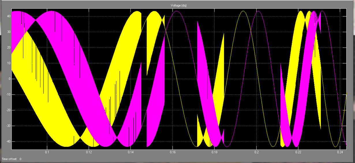
  • Case anyone was wondering - below shows a simulated PWM sine wave 2 axis (dq) in a 3 phase AC motor, wave appears very sinusoidal. The 2nd-3rd (qs-bldc) captured 20kHz and motor shaft speed roughly 10 RPM with 60Hz Hall code changes, 24vdc 200ma.  

    25Khz PWM - rotor roughly 0-30 RPM

    20kHz PWM:

    Notice modulated flag sine wave center inverts, 12.5kHz PWM @60Hz Hall code changes.  

  • Hi there, I am also interested in RDK-BLDC, and have contacted TI store trying to buy the whole kit, but unfortunately, the kit is no longer available. I have few of these microcontrollers in the stash so for evaluating I would be fine, but since I cant buy the kit I don't have the PCB. I read that PCB gerber files went with the CD that was shipped with this kit and was wondering does anybody have these so I can build a board for myself. Would evaluate and then port to Tiva C series. It would be an overkill for me now to do the whole PCB design for evaluation purposes. Any ideas? I am ready to buy a kit, or just a CD, or maybe TI support can help me with this. Thank You!
  • Hi Marko,
    We have migrated software to TM4C1294 and it has similar issues remaining to (LM3S8971 NDNR) PWM switching modes. Recommend the time required to migrate LM3S code plus debug time it might benefit you to try Piccolo F28027F coupled to a DRV8305 and Instaspin motorware control suite. The F280x ePWM peripheral controller can produce many very complex wave forms, take a look.

    If you must have the LM3S Gerber file perhaps can find available somewhere archived.

  • Thank you,
    I would be grateful if you can find those gerber files, that would help me very much! I already looked at the motorware suite but for this particular application I find the RDK-BLDC platform easier to integrate.
  • Marko you do know that MCU is NDNR no longer manufactured by TI. There was and still is an on going issue with PWM generator comparator B both MCU's. The BLDC software has recently been discovered was jamming comparator B in slow decay mode and basically Cloaks a half witted dead band pulse pwmB when it is actually disabled.

    A recent WA patch (Not posted) for TM4C1294 seems to (finally) allow 1/2 bridge dead band to remain enabled during commutation. However the pulse width CMPB refuse to drop below the initial setting or follow pwmA pulse width during synchronous updates in FOC motor startup, without patch.  The good thing is the pulse width pwmB when set lower than 95% initially, produces low and high side PWM is (very efficient) than without a patch and forcing CMPB near 100% pulse width as the code originally did.

    Testing this new patch setting 0.2us minimum pulse width seems to build a more (dynamic) slow decay mode for motors demanding large startup currents, mostly drives high side in very few PWM pulses.  FYI the FOC sensorless commutation transitions from an open to closed loop mode and forces slow decay during open loop. Hard to know about Halls mode and starting in fast decay though suspect there are similar issues in CMPB being jammed if ever starting a motor in slow decay, without patching. Suspect all that was due to the odd behavior of CMPB and the synchronous update patch now gives very even symmetry in the bridge PWM motor currents. That insane behavior of CMPB pulse width being static is still not proper and that is why I suggested Piccolo + DRV8305.

    Highly advise not to get tangled in this can of smelly worms though much is far easier to debug using the TM4C1294 built in ICDI.

    /cfs-file/__key/communityserver-discussions-components-files/908/Stellaris-LM3S8971-Gerber-RDK-TQFP_2D00_100.zip

  • Thank You BP101,
    But there are no gerber files of the board inside, just the footprint of the LM3S8971 .
  • That's a shame, had believed long ago that was the Gerber print file of entire PCB.