This thread has been locked.

If you have a related question, please click the "Ask a related question" button in the top right corner. The newly created question will be automatically linked to this question.

Why isn't my SysCtlDelay() as small as it could be? NeoPixels & WS2812 TM4C

Other Parts Discussed in Thread: EK-TM4C1294XL, TM4C1294NCPDT, TM4C129XNCZAD

Evening, 

I've been working on a very simple way for the the TIVA C to use NeoPixels just using a standard GPIO port and just using SysCtlDelay()

To drive the neopixels I need to have have output pulses in the 100s of ns (400 for the lowest pulse). 
a bit "1" is  800ns on 450ns off && a bit "0" is 400ns on and 850ns off
The neopixels themselves only run off of 800kHz (which shouldn't be a stretch for a 120MHz board). 8 bits for each colour, 24 per pixel. 

The key part is getting down to the 400ns mark for the 'off' pulse (in my code as Pixel_Low function).  I have tried timers and other delay methods to no avail. 

I have set my clock to 120MHz (I'm fairly sure...) which will give me clock cycles of 8.3ns
Using the SysCltDelay() this should delay the device for a few clock cycles (i'd guess around 3-5?) giving me a delay of around 40ns (a guess really), but not as large as it is currently giving me.

So why wont my output give me anything less than 1.3us? Is my clock not set right? Is SysCtlDelay running off of a different clock? At the moment all I am getting is full brightness on all the pixels, as its not recognising any '0' that i'm sending it

Below is my code, i hope its simple to understand & any help would be appreciated.  

Will:)

//Will Yates - NeoPixel_Simple

#include <stdint.h>
#include <stdbool.h>
#include "inc/hw_memmap.h"
#include "driverlib/gpio.h"
#include "driverlib/sysctl.h"

//*****************************************************************************

#define NUM_LED 16 // teststrip: 8     ring: 16      strip: 144

//*****************************************************************************
//***************************************************************************//
//These two functions translate the 24bits for each LED to something that    //
//the WS2812b LEDs can understand. The datasheet is useless		     //															 //      ________                                                             //
//	        |_____ '1' is a 800ns pulse then low (can be high forever)   //
//	_____
//             |________ '0' is a 400ns pulse (only key pulse lengt )								 //
//  the only thing that really matters is that the high pulses dont overlap  //
//***************************************************************************//
void Pixel_High()  // function for sending a high pulse
{
	GPIOPinWrite(GPIO_PORTN_BASE, GPIO_PIN_0, GPIO_PIN_0);
	SysCtlDelay(6);		//this needs to be the equv of 800ns (ish)
	GPIOPinWrite(GPIO_PORTN_BASE, GPIO_PIN_0, 0x00);
	SysCtlDelay(2);     //length of this doesn't really matter
}

void Pixel_Low() // function for sending the low pulse
{
	GPIOPinWrite(GPIO_PORTN_BASE, GPIO_PIN_0, GPIO_PIN_0);
	SysCtlDelay(1);		//this needs to be less than 400ns
	GPIOPinWrite(GPIO_PORTN_BASE, GPIO_PIN_0, 0x00);
	SysCtlDelay(6);		//length of this doesnt really matter
}
//*****************************************************************************
//***************************************************************************//
//	This function is called to output the data onto the LEDs	     //
//		it calls the translate functions at the top  		     //
//***************************************************************************//
void Pixel_GRB(uint8_t Green_Byte,uint8_t Red_Byte,uint8_t Blue_Byte)
{
	uint8_t pixel_bit;   // pixel_bit is the individual LED in the array
	for(pixel_bit=0;pixel_bit<NUM_LED;pixel_bit++){ //works through every pixel
			if((Green_Byte<<pixel_bit) & 0x80) //checks for a 1
				Pixel_High();  //goes to function for 1 pulse
			else Pixel_Low();	//goes to function for 1 pulse
			}
	for(pixel_bit=0;pixel_bit<NUM_LED;pixel_bit++){//sends info for the Red_Byte
			if((Red_Byte<<pixel_bit) & 0x80)
				Pixel_High();
			else Pixel_Low();
			}
	for(pixel_bit=0;pixel_bit<NUM_LED;pixel_bit++){//sends info for the Blue_Byte
			if((Blue_Byte<<pixel_bit) & 0x80)
				Pixel_High();
			else Pixel_Low();
			}
}
//*****************************************************************************
int
main(void)
{
	SysCtlDelay(10000000);
	//Set clock frequency
	SysCtlClockFreqSet(SYSCTL_OSC_MAIN
						| SYSCTL_USE_PLL
						| SYSCTL_CFG_VCO_480
						, 120000000); //set clock for 120MHz

	//Enable GPIO port
    SysCtlPeripheralEnable(SYSCTL_PERIPH_GPION);
    while(!SysCtlPeripheralReady(SYSCTL_PERIPH_GPION))
    {
    }
    GPIOPinTypeGPIOOutput(GPIO_PORTN_BASE, GPIO_PIN_0);

    //reset pixels
    GPIOPinWrite(GPIO_PORTN_BASE, GPIO_PIN_0, 0x00);
    SysCtlDelay(20000);

    //write the same value to all the LEDs
    int white;
    for(white = 0; white<NUM_LED; white++){
    	Pixel_GRB(100,0,0);
    }

    //Blink LED so that I know send is finished
    while(1)
        {

            GPIOPinWrite(GPIO_PORTN_BASE, GPIO_PIN_0, GPIO_PIN_0);

            SysCtlDelay(3000000);

            GPIOPinWrite(GPIO_PORTN_BASE, GPIO_PIN_0, 0x0);

            SysCtlDelay(3000000);

            Pixel_GRB(0,0,0); //reset LEDs to black
        }
}

Will

  • Hello Will,

    Execution of the SysCtlDelay is based on the placement of the code w.r.t Flash Prefetch buffer. So at 120MHz a delay of 3 would mean 3*3 (as it takes 3 cycles for each count), or 9 System Clock Cycles + the Flash prefetch buffer of 7 when the API is across a prefetch boundary = 16 system clock cycles.

    This is rather inaccurate when delay needs to be timed well for such applications. Timers are better to such processing as they do not rely on Flash prefetch conditions but only on the system clock. A timer can be made to do the same and it seems that the configuration may not be done correctly.

    Please also refer to the following post.

    e2e.ti.com/.../1268077

    Regards
    Amit
  • Will Yates said:
     I have tried timers and other delay methods to no avail. 

    While "SysCtlDelay()" is attractive - it is the MCU Timers which best serve your task.   The report of, "To no avail" is kin to, "Does not Work!"   It conveys no/zero usable data for analysis - that is not meant to be cruel/critical - but to convey fact.

    As vendor's Amit has written - most any (possibly ALL) of your MCU's Timers should (easily) meet your 400nS pulse requirement.

    You likely tested via use of a GPIO - and if you failed to choose the, "High Speed GPIO Bus" your outputs would be slowed.  (broadened)   And it is precisely (here) that, "to no avail" so fails you - and now we.  (your helpers)

    Further study of the Timer AND GPIO section - w/in your MCU manual - will (surely) improve results...

  • cb1- said:
    While "SysCtlDelay()" is attractive - it is the MCU Timers which best serve your task.

    Damn straight. Delay loops for timing are a best forgotten holdover from processors with no timing resources. Only look at them if the plenitude of timers on the micro cannot do the job.

    Robert

  • Agreed, Sir.    You/I recall when you were lucky to get 2 or maybe (sometimes) 3 Timers - such was "pig-heaven."  

    SysCtlDelay() lands as either (or both):

    • over-promoted
    • inadequately explained - especially "limitation-wise."

    Users are "smart" to avoid complexity - yet then (too often) cast adrift by the absence of usage safeguards...

  • Will Yates said:
    To drive the neopixels I need to have have output pulses in the 100s of ns (400 for the lowest pulse). 
    a bit "1" is  800ns on 450ns off && a bit "0" is 400ns on and 850ns off
    The neopixels themselves only run off of 800kHz (which shouldn't be a stretch for a 120MHz board). 8 bits for each colour, 24 per pixel. 

    The key part is getting down to the 400ns mark for the 'off' pulse (in my code as Pixel_Low function).  I have tried timers and other delay methods to no avail.

    The Data Timing time specification for the WS2812B:

    Rather than have to bit-bang the WS2812B data using a GPIO pin which requires controlled software timing, I was wondering if would be simpler to use the QSSI SSI3XDAT0 output to generate the WS2812B data. If the WS2812B T0L time is generated as 0.8 us and the T1L time is 0.4 us then the Data transfer time TH+TL would be 1.2us and would still be in tolerance and could set the QSSI as:

    - Legacy SSI mode

    - 6-bit data

    - 5MHz SSI clock frequency, i.e. the duration of each SSI bit is 0.2 us

    - Use a pull-up on the SSI3XDAT0 output so than when the QSSI transmitter is idle the WS2812B data input is pulled high.

    That would mean transmitting either of the two SSI values would generate the timing for either of the WS2812B bit values:

    - 0x30 is a zero bit for the WS2812B

    - 0x3C is a one bit for the WS2812B

    Therefore, every write of either 0x30 or 0x3C to the QSSI Data register would cause the output of one WS2812B bit with the required timing.

  • Thank you for your suggestion! It's something I did consider, and is a route that has been used a lot judging by all the YouTube and libraries out there. However, sadly my PCB is made and this is the pin that i chose (foolishly), should i do more with these LEDs then this would probably be the route I'd use.
  • Ahhh, then clarification is needed cb1!!

    Timerwise I used i just declared a loop : "volatile uint32_t ui32Loop; " then incremented within a for loop as taken from 'blinky':
    for(ui32Loop = 0; ui32Loop < 200000; ui32Loop++) {}
    -- this still didn't give me my desired output


    I also used ___delay_cycles , which i'm guessing did very similar to the method i previously used. again same timing issues.


    I'm currently looking into the use of the High Speed GPIO Bus!
  • Thanks Amit, I'm glad I can understand that a little more now,

    The actual timing really doesn't need to be as accurate as the data sheet and other libraries make you think, it just needs to be small enough for the 0 code high bit, or T0H. The reset can be as small as 9us, the T1H can be the length of a piece of string, T0L & T1L don't matter as long they aren't the length of the reset pulse. T0H & T1H need to be above & below 400ns but where it falls above & below that doesn't matter. Everything has a lot of leeway, so accuracy is really not a problem, its just the delay wont be small enough.

    Hence the reason I thought I could be cheeky and only use SysCtlDelay(),
  • And why not use a timer? Since they modify the pin directly your SW just has to set them up.

    Although queuing on the SPI is probably more straightforward (maybe even with modifying the board)

    Robert
  • Hello Will,

    The post from Luis I know is working, so it would accelerate your work be reusing the same

    Regards
    Amit
  • I decided to go with the timer method, which I am still working on. Thanks for all the help and suggestions.

    However in the process I solved my problem. It was to do with how I set my clock. Still unsure why that would be, but I'm not going to question it too much.

    So for those who are simple like me, here is the KISS version of code:
    github.com/.../NeoPixel-Simplistic.git
  • If the device requires/expects a logic high @ idle - and the SPI pin/port is employed - I question the (suggested use) of a pull-up.   SPI - to my knowledge - does not operate under "Open Drain" but instead via "Push-Pull."  

    One poster here argued: "Use a pull-up on the SSI3XDAT0 output so than when the QSSI transmitter is idle the WS2812B data input is pulled high."   Yet - if the pull-up is strong enough to "overcome" the "normal (low) logic level provided by the MCU - is not this method, "Asking for - even inviting trouble?"

    This pull-up idea then presents the possibility of:

    • conflicting w/the (normal) MCU's SPI pin-data state when at idle
    • being over-ridden by the MCU's SPI pin-data state when at idle  (should the pull-up dominate the MCU's output - and they are in contention - the MCU may suffer damage

    Neither proves good - I'd avoid this suggestion.

    In Will's response he soldiers on w/"Delay" - note that Amit, Robert & myself have all voted for Timer usage, instead.

    Unknown (by me) is whether the use of a Timer pin tied to a "fast" GPIO Port will succeed in (further) shrinking minimum Timer Output pulse width.

  • Good for you - and HURRAY for your choice of - and success with (obviously) and reporting of such - "KISS"-based Victory!"
  • cb1- said:
    If the device requires/expects a logic high @ idle - and the SPI pin/port is employed - I question the (suggested use) of a pull-up.   SPI - to my knowledge - does not operate under "Open Drain" but instead via "Push-Pull."

    The reason I suggested the pull-up is that the the SPI transmit data line is documented as being tri-stated during idle periods.

    I haven't tested it, but I assumed a suitable pull-up resistor value would allow the WS2812 input to be seen as a high during idle periods, but would be driven low by the SPI module when sending data (when the SPI transmit data line is push-pull).

  • Chester Gillon said:
    the SPI transmit data line is documented as being tri-stated during idle periods.

    Thank you - I don't believe that to be normal/customary practice though - certainly is NOT the case across the ARM MCU market leaders' devices.

    "Floating" the data-line usually - but not always - has the potential to "wreak havoc" upon all (signal) interconnected devices.   Firm/I are curious as to "Why this has been done?"   (and why not at/by the ARM market leaders?)

    At the minimum - that (excess) pull-up may cause some "slew" upon the SPI pin's (active) high to low transition - that is unlikely to be desirable...

  • Will Yates said:
    I decided to go with the timer method, which I am still working on.

    Out of curiosity, I created the following example for a EK-TM4C1294XL which uses a timer to control the generated bit timing. I don't have any WS2812B LEDs to test it with, but instead used an LSA to look at the generated bit timings.

    The program is:

    /*
     * main.c
     */
    #include <stdint.h>
    #include <stdbool.h>
    #include <string.h>
    
    #include <inc/hw_memmap.h>
    #include <inc/hw_timer.h>
    #include <inc/hw_gpio.h>
    #include <driverlib/sysctl.h>
    #include <driverlib/timer.h>
    #include <driverlib/gpio.h>
    
    /* Used to build test sequence of bytes to transmit */
    #define TEST_SEQUENCE_LEN 256
    static uint8_t test_data[TEST_SEQUENCE_LEN];
    
    /**
     * @brief Trasnmit a sequence of bytes to a WS2812B, using bit-banged GPIO on PG1
     * @details Using timer0 set a free-running 32-bit count at the CPU frequency to control the bit timing.
     *          Interrupts should be disabled, otherwise the timing might be disrupted.
     *
     *          There are no function calls to TivaWare while changing the WS2812B data to minisise
     *          variations in the generated bit timing, and direct register access is used to read
     *          the timer 0 value and change the GPIO PG1 output.
     * @param[in] tx_data Array of data to transmit to the WS2812B
     * @param[in] tx_data_len Number of bytes in tx_data[] to transmit
     * @param[in] clock_freq The CPU frequency, used to calculate the bit times
     */
    static void transmit_WS2812B_byte_sequence (const uint8_t *tx_data, size_t tx_data_len, const uint32_t clock_freq)
    {
        /* Calculate the the number of clock ticks per WS2812B data transfer time interval.
         * With clock_freq set to 120MHz, these calculate an exact integer multiple of clock ticks. */
        const int32_t T0H_ticks = (int32_t) (clock_freq / (1000000000 / 400));
        const int32_t T1H_ticks = (int32_t) (clock_freq / (1000000000 / 800));
        const int32_t T0L_ticks = (int32_t) (clock_freq / (1000000000 / 850));
        const int32_t T1L_ticks = (int32_t) (clock_freq / (1000000000 / 450));
    
        /* Set access to the current Timer 0 value, to avoid the overhead of a call to TimerValueGet() */
        volatile int32_t *const timer0_TAR = (volatile int32_t *) (TIMER0_BASE + TIMER_O_TAR);
    
        /* Set access to the bit-banded GPIO register to change PG1 which is the WS2812B data,
         * to avoid the overhead of a call to GPIOPinWrite() */
        volatile uint32_t *const WS2812B_gpio_data = (volatile uint32_t *) (GPIO_PORTG_AHB_BASE + GPIO_O_DATA + (GPIO_PIN_1 << 2));
    
        /* Set the initial time to change the WS2812B data to the current timer value plus the maximum duration
         * bit time - to give some setup time to get into the loop. */
        int32_t next_bit_change_time = (*timer0_TAR) + T0L_ticks;
    
        uint32_t bit;
    
        while (tx_data_len > 0)
        {
            for (bit = 0; bit < 8; bit++)
            {
                if ((*tx_data & (1u << bit)) != 0)
                {
                    /* Output a one bit to the WS2812B */
                    while ((next_bit_change_time - (*timer0_TAR)) >= 0)
                    {
                    }
                    *WS2812B_gpio_data = GPIO_PIN_1;
                    next_bit_change_time += T1H_ticks;
    
                    while ((next_bit_change_time - (*timer0_TAR)) >= 0)
                    {
                    }
                    *WS2812B_gpio_data = 0;
                    next_bit_change_time += T1L_ticks;
                }
                else
                {
                    /* Output a zero bit to the WS2812B */
                    while ((next_bit_change_time - (*timer0_TAR)) >= 0)
                    {
                    }
                    *WS2812B_gpio_data = GPIO_PIN_1;
                    next_bit_change_time += T0H_ticks;
    
                    while ((next_bit_change_time - (*timer0_TAR)) >= 0)
                    {
                    }
                    *WS2812B_gpio_data = 0;
                    next_bit_change_time += T0L_ticks;
                }
            }
    
            tx_data_len--;
            tx_data++;
        }
    
        /* Set the WS2812B data to a idle at the end of byte sequence */
        while ((next_bit_change_time - (*timer0_TAR)) >= 0)
        {
        }
        *WS2812B_gpio_data = GPIO_PIN_1;
    }
    
    int main(void)
    {
        uint32_t clock_freq;
    
        clock_freq = SysCtlClockFreqSet (SYSCTL_XTAL_25MHZ | SYSCTL_OSC_MAIN | SYSCTL_USE_PLL | SYSCTL_CFG_VCO_480, 120000000);
    
        /* Configure timer0 as a free-running up counter over the entire 32-bit range */
        SysCtlPeripheralEnable (SYSCTL_PERIPH_TIMER0);
        TimerClockSourceSet (TIMER0_BASE, TIMER_CLOCK_SYSTEM);
        TimerConfigure (TIMER0_BASE, TIMER_CFG_PERIODIC_UP);
        TimerLoadSet (TIMER0_BASE, TIMER_A, 0xffffffff);
        TimerEnable (TIMER0_BASE, TIMER_A);
    
        /* Enable GPIO PG1 for transmitting the WS2812B, and set to the idle state of high */
        SysCtlPeripheralEnable (SYSCTL_PERIPH_GPIOG);
        SysCtlGPIOAHBEnable (SYSCTL_PERIPH_GPIOG);
        GPIOPinTypeGPIOOutput (GPIO_PORTG_AHB_BASE, GPIO_PIN_1);
        GPIOPinWrite (GPIO_PORTG_AHB_BASE, GPIO_PIN_1, GPIO_PIN_1);
    
        /* Enable PK4 as a LSA trigger, which is high around the call to transmit_WS2812B_byte_sequence */
        SysCtlPeripheralEnable (SYSCTL_PERIPH_GPIOK);
        GPIOPinTypeGPIOOutput (GPIO_PORTK_BASE, GPIO_PIN_4);
        GPIOPinWrite (GPIO_PORTK_BASE, GPIO_PIN_4, 0);
    
        /* Transmit test sequence of repeating byte values, to enable an LSA to capture the output on PG1 */
        memset (test_data, 0, sizeof(test_data));
        GPIOPinWrite (GPIO_PORTK_BASE, GPIO_PIN_4, GPIO_PIN_4);
        transmit_WS2812B_byte_sequence (test_data, sizeof(test_data), clock_freq);
        GPIOPinWrite (GPIO_PORTK_BASE, GPIO_PIN_4, 0);
    
        memset (test_data, 0xff, sizeof(test_data));
        GPIOPinWrite (GPIO_PORTK_BASE, GPIO_PIN_4, GPIO_PIN_4);
        transmit_WS2812B_byte_sequence (test_data, sizeof(test_data), clock_freq);
        GPIOPinWrite (GPIO_PORTK_BASE, GPIO_PIN_4, 0);
    
        memset (test_data, 0x55, sizeof(test_data));
        GPIOPinWrite (GPIO_PORTK_BASE, GPIO_PIN_4, GPIO_PIN_4);
        transmit_WS2812B_byte_sequence (test_data, sizeof(test_data), clock_freq);
        GPIOPinWrite (GPIO_PORTK_BASE, GPIO_PIN_4, 0);
    
        memset (test_data, 0xaa, sizeof(test_data));
        GPIOPinWrite (GPIO_PORTK_BASE, GPIO_PIN_4, GPIO_PIN_4);
        transmit_WS2812B_byte_sequence (test_data, sizeof(test_data), clock_freq);
        GPIOPinWrite (GPIO_PORTK_BASE, GPIO_PIN_4, 0);
    
        return 0;
    }
    

    With the compiler optimization level set to "2 Global Optimizations" the LSA (with a 10ns resolution) showed the bit times generated were of the order of +/-50ns of the required values, which is within the allowed +/-150ns timing tolerance required by the WS2812B.

    Note the use of the timer avoids the need to hard-code specific delay values.

  • Chester Gillon said:
    Note the use of the timer avoids the need to hard-code specific delay values.

    @Chester/interested others...

    Bravo on the above (use of an MCU Timer) and your recognition of the value of "Sequencing Bits" via 0x55 & 0xAA.

    Now to, "Set the record straight wrt the "Default state" of SPI_TX - I copy/paste from must current TM4C123 (not poster's - but one I have.)

    Again - firm/I most often use ARM MCUs from multiple sources - always seeking best blend: "Features, Performance, Availability, Product Span & Price."   Many of my firm's clients are (still) disappointed by the (severe) limitation of Cortex "M" devices - this vendor.  (i.e. NO M0, M0+, M3, M7 and >120MHz M4)  

    And - as we often use MCUs from another - I can report that the ONLY SPI Format in which SPI_TX behaves as, "Tri-State @ idle" is under, "TI Synchronous - Serial Frame Format!"   Which proves (very) much a minority usage case.   (and not too often found - other than here)

    Far more popular & employed SPI Formats (to include SPI-based ICs btw) are, "Freescale (in 4 "flavors") and Microwire.   And ALL return SPI_TX to LOW when idle!   (negating the hoped for benefit of a pull-up resistor.)  

    Here's confirmation not from brand "X, Y or Z" - but from this vendor's TM4C123 data-sheets:

    Note that the identical "forced to LOW" occurs in the 2 remaining "Freescale SPI Modes!"   And then Microwire:

  • cb1- said:
    Now to, "Set the record straight wrt the "Default state" of SPI_TX - I copy/paste from must current TM4C123 (not poster's - but one I have.)

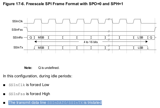
    I have just doubled checked the TM4C1294NCPDT data sheet and for the TM4C129 series QSSI module the transmit data line SSInDAT0/SSInTX is reported to be tristated whenever the QSSI is idle, in all modes:

  • Look again - and more closely - 100 (USD) says that's "Cut/Paste" ERROR!

    The timing chart is JUST as I described - SSIxTX drives LOW.

    There is NO advantage to floating that line - none - foolish to persist...
  • cb1- said:
    Look again - and more closely - 100 (USD) says that's "Cut/Paste" ERROR!

     The timing chart is JUST as I described - SSIxTX drives LOW.

    Looking back at the history in the TM4C129 datasheet it appears there was a deliberate change to the text describing the operation of the transmit data line when the QSSI module is idle in the Freescale SPI Frame Format.

    1) In the TM4C129XNCZAD datasheet dated October 19, 2013:

    a) The Texas Instruments Synchronous Serial Frame Format section says:

    In this mode, SSIClk and SSIFss are forced Low, and the transmit data line SSInDAT0/SSInTX is tristated whenever the QSSI is idle.

    b) The Freescale SPI Frame Format sections say:

    In this configuration, during idle periods:

    ■ The transmit data line SSInDAT0/SSInTX is arbitrarily forced Low

    2) In the TM4C1294NCPDT datasheet dated June 18, 2014:

    a) The June 2014 revision history says:

    In SSI chapter:
    – Noted that during idle periods the transmit data line SSInTx is tristated.

    b) The Freescale SPI Frame Format sections have been changed to say:

    In this configuration, during idle periods:

    ■ The transmit data line SSInDAT0/SSInTX is tristated

    While I haven't myself tested the behavior of the QSSI transmit data line in Freescale SPI Frame Format, my guess is that the text is correct and the issue is that the Freescale SPI Format timing diagrams weren't updated to show the transmit data line SSInDAT0/SSInTX being tristated when idle.

    Perhaps Amit can clarify this, and request the datasheets are updated to ensure the text and timing diagrams are consistent.

  • Switching (as has been done here) from "normal/customary" single data bit, SPI (Freescale & Microwire by far, predominate in format popularity/usage) to single vendor's (now QSSI) wanders bit too far (and too single vendor focused) for firm/my taste.

    Unanswered still, "Why would a single SPI_TX data line (input to some awaiting device) be ordered to "float" when in idle?  (and that "offense" is magnified when QSSI enters the arena!)   In the past - signals were ordered into "tri-state" (or hi-Z) when the bus was shared among devices - I don't believe that's the case w/SPI - it should not be - that multiple SPI "Masters" attach their SPI_TX - to the same Slave.   (if such a case existed - and the slave was (some way/how) accepting/welcoming of the floating data line - then that "float" (may) prove acceptable.)

    Of course ONE SPI Master may be "bussed" to MULTiPLE SPI Slaves.   But such sees the ONE, Master, SPI_TX line tied to many Slaves - thus "float" of SPI_TX (appears) to  serve no purpose!

    Agreed that vendor (inside) expertise is required - especially in light of the BIG switch between TM4C123's handling of SPI_TX (during idle) and the newer data you've presented.   Why that expertise (multiple, valuable, known (and hoarded) vendor tech-facts must be "pried out" (rather than freely presented) is fodder for (another) discussion...

  • There is another reason to consider a pullup, the transmit line will float until it is changed to an output.

    Robert
  • I must (almost) agree w/that explanation - yet question your use of "another?"   (another implies an earlier reason - none other has been submitted.)

    The timing charts I supplied - directly from this vendor's TM4C123 device - are fairly standard across "ARM-MCU Land." (Our M0's, M3's, M4's & M7's all follow that, "SPI_TX ordered low on idle."

    Let's reason by extension (to the limit) if one such "pull-up" R proves beneficial - why not (burden) each/every SPI line?

    You & I (may) have used SPI w/some success for beyond a decade - never/ever - (well over 25K boards produced/sold) did we employ a pull-up on other than the SPI_CS line.

    I don't believe the market leaders for these devices enforce or recommend such "add-ons" - and I (still) have not received a "solid" justification!

  • This code is fantastic & has really helped me (I can confirm it does work & the timing is spot on!), thank you for taking the time to do that! My next problem is that I cannot seem to properly send the data I want to the individual LEDs, only a single LED will light or it wont be the colours that I want, this is namely because I do not fully understand the code.

    The bit generation I actually understand along with the timers, but where I struggle is when you start calling "memset". I'm trying to create a function; "void LED_data (uint8_t pixel, uint8_t r, uint8_t g, uint8_t b)" which will send the data to a particular LED, but from what I can understand from the code you send all the data in a massive string rather than an LED at a time. So how could I make a function thats makes it simpler to call an LED?

    Or would it be better to have a function that called "Pixel_Low" and "Pixel_High" which would simply be called as I had originally, but with more precise timing?

    I want to model it on the Adafruit NeoPixel library as much as possible, so I can utilise the Arduino code that is out there already as much as possible,


    Sorry if this is too simple for you guys but I really do appreciate the help, I'm a fairly slow learner, but I'll get there eventually!
  • Will Yates said:
    The bit generation I actually understand along with the timers, but where I struggle is when you start calling "memset". I'm trying to create a function; "void LED_data (uint8_t pixel, uint8_t r, uint8_t g, uint8_t b)" which will send the data to a particular LED, but from what I can understand from the code you send all the data in a massive string rather than an LED at a time.

    The example code I gave wasn't structured to actually update LEDs, but was just to output a repeating sequence of bits to be able to measure the generated bit timing. The memset() call was just used to initialize different test bit patterns.

    Will Yates said:
    I want to model it on the Adafruit NeoPixel library as much as possible, so I can utilise the Arduino code that is out there already as much as possible

    Looking at the source in https://github.com/adafruit/Adafruit_NeoPixel/blob/master/Adafruit_NeoPixel.cpp shows the Adafruit_NeoPixel class has the pixels array which contains the contents of all the pixels in the LED strip and has functions to get/set the value of individual pixels and the show() function which sends all pixels values to the LED strip. Since the WS2812B LEDs are serially daisy-chained the LEDs are not individually addressable, which means every change has to output the values for all LEDs in the strip.

    I think what you need to do is to base your code upon the Adafruit_NeoPixel class, changing the implementation of Adafruit_NeoPixel::show to the transmit_WS2812B_byte_sequence() function from my previous example.

  • Hello All,

    The text seems to be fine. The diagram representation of the SSInTX line for the legacy mode for tri state is not correct,

    Regards
    Amit
  • Hi Amit,

    Pest alert - yet this (highly foreign, device-centric) post has "so" expanded - some of the fine details have become clouded.

    Recall that my firm has been here since forum's start under LMI. And I can report that SPI_TX on each/every LM3S device - and upon 2 LX4F devices my firm has employed - saw the SPI_TX signal line, "drive to ground" when idle. We monitored that (SPI_TX) via a low current Led - which could only illuminate when SPI_TX approached ground. (we did this as we had a "round-robin" communication set-up - and it was helpful (and comforting) to see the SPI_TX "become active" as the messages "wound thru" the various devices.)

    I can state that many/most competitive M4s, M3s, M0s and M7s pull their SPI_TX to ground @ idle - as well.

    Perhaps you know - or could answer - "What is the purpose of having SPI_TX "go tri-state" when idle?" It seems extremely unlikely that SPI_TX would appear in common w/other SPI_TX signals (from other MCUs judged "Master.")    And in conformance w/"What's good for the goose" - why limit "just" SPI_TX to this tri-state when idle treatment?   Why not all such SPI pins?   

    My "insider knowledge" beacon is flashing that this was done (here) to (possibly) accommodate the sharing of SPI_TX with one of the (new) I2C signals.   If that's the case - really there is little advantage to the SPI network - and a "forest" of pull-ups may become "de rigueur."

    [edit] perhaps your firm's use of "SSI" rather than the (long established) convention of "SPI" proves pivotal?   I can't state that we've conducted a "deep" search of our SPI Peripheral ICs - yet those most used place no requirement for SPI_TX to, "go tri-state" when idle - instead they seek "real/valid" logic levels - even when the SPI bus is idle...