Dear Sir
Iam facing some issue related with ADC.Please go through the test setup and problem statement given below
Details of the Setup
Microcontroller :-TM4C1290NCPDT
IDE:-CCS 6.0.1.00040
Compiler:-TI V 5.1.11
Emulator:-XDS100V2
Target board:-customized target board
Crystal Frequency:-8Mhz
System Frequency:-120Mhz
ADC sampling frequency :-8Hz (This frequency is achieved by using Timer Trigger mode)
ADC Ref:-3V
ADC input :-0 to 3V DC
ADC configuration :-Single ended
ADC 0 sampling logic:-
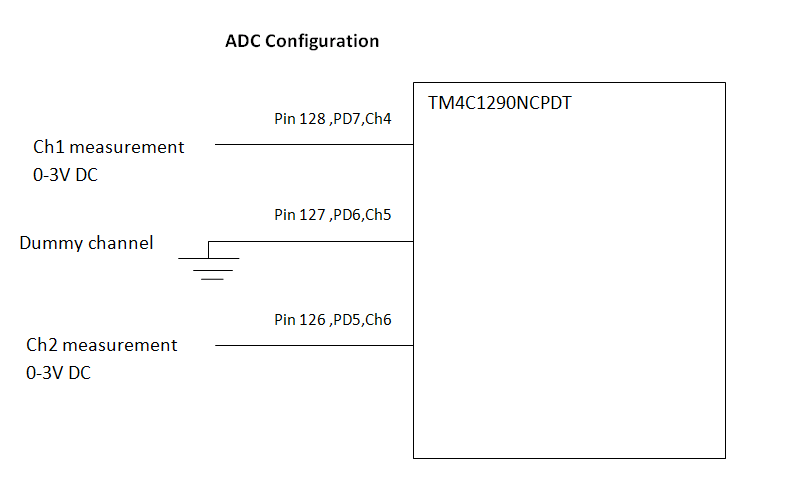
ADC is triggered using Timer trigger(Timer 7 is used).It will trigger the ADC every 125mS and data is collected using ADC ISR. Sequence 2 is used.4 channels are configured in sequence 2 and interrupt is enabled at the step4 of sequencer.In that 4 channels two channels are used for measurement and the remaining two used as a Dummy channel to avoid cross talk between measurement channels.Input to the Dummy channel is connected to ground to ensure 0 input
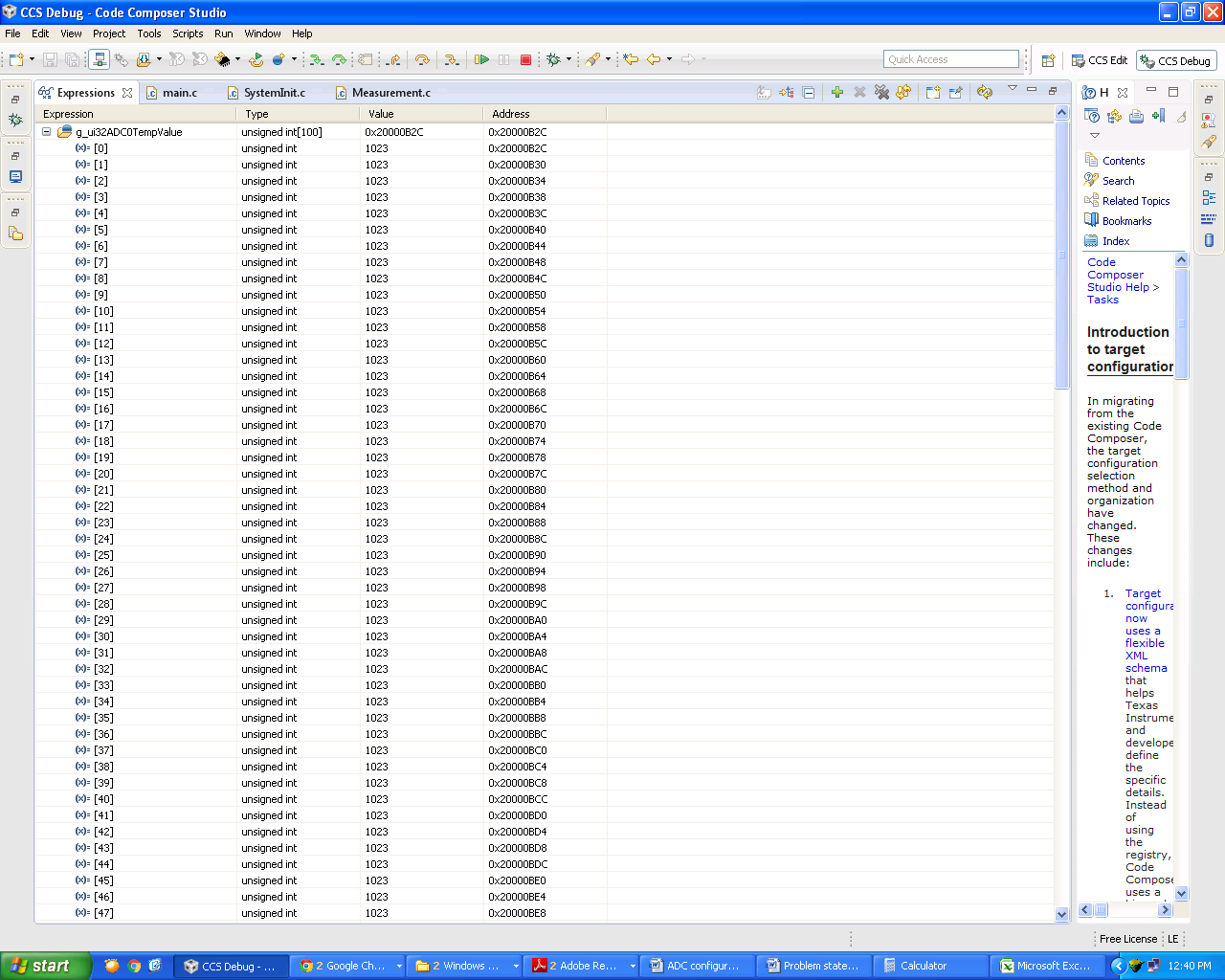
Problem statement
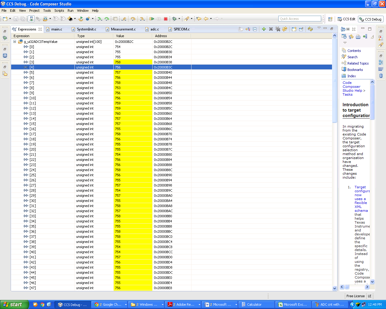
Whenever the input to ADC is given corresponding to 2^n-1 (ie 2047,1023, 511, 255,127,63 etc) value then ADC count is freezing to the corresponding 2^n-1 value. We collected these data in a array of 100 values at every 125mS. All values are getting rock steady to these magical values(2^n-1). Input to ADC is DC with some unwanted noise,so as per the input, the ADC count should vary in between 5-15 counts but as soon the ADC count reaches to these magical value there is no single count variation.For other count values it is working as expected.
To come out of these magical values the input need to change substantially in value corresponding to 20 - 30 counts.It will work fine as soon as it come out of the magical value.These problem is happening in measurement ch1 as well as measurement ch2. One more finding is, problem in one channel is not affecting other
Test case:
742mVDC is corresponds to 1023counts and these counts remain constant for a input variation from 735mVDC to 780mVDC .But actually it should vary from 1013 to 1076counts.For other than magical values ADC counts varing corresponds to the input variation even for 2mVDC
Please find the attached for code snippet,results and block diagram.
Thanks in advance for any suggestions.
//ADC
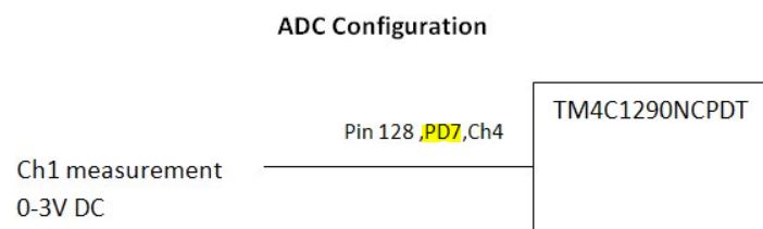
#define DEF_CH1ADC_CAL1 GPIO_PIN_7 //PD7
#define DEF_ADC_DUMMY GPIO_PIN_6 //PD6.....This Pin is used for Dummy ADC //read to avoid cross talk
#define DEF_CH2ADC_CAL1 GPIO_PIN_5 //PD5
uint32_t g_ui32ADC0Value[8];
uint32_t g_ui32ADC0TempValue[100];
uint8_t g_ui8ADCTestcnt=0;
uint32_t g_ui32SysClock;
Void main(void)
{
SysCtlPeripheralReset(SYSCTL_PERIPH_ADC0);
g_ui32SysClock = MAP_SysCtlClockFreqSet((SYSCTL_XTAL_8MHZ |SYSCTL_OSC_MAIN |SYSCTL_USE_PLL |SYSCTL_CFG_VCO_480), 120000000);
IntMasterEnable();
MAP_SysCtlPeripheralEnable(SYSCTL_PERIPH_GPIOD);//for ADC
MAP_SysCtlPeripheralEnable(SYSCTL_PERIPH_ADC0);
MAP_SysCtlPeripheralEnable(SYSCTL_PERIPH_TIMER7);
MAP_SysCtlDelay(51); //51*3 clk cycles=1.275uS
MAP_TimerDisable(TIMER7_BASE,TIMER_BOTH);
MAP_TimerConfigure(TIMER7_BASE,TIMER_CFG_PERIODIC);
MAP_TimerControlTrigger(TIMER7_BASE,TIMER_BOTH,true);
MAP_TimerADCEventSet(TIMER7_BASE,TIMER_ADC_TIMEOUT_A);
MAP_TimerLoadSet(TIMER7_BASE, TIMER_BOTH, 15006002);//for 125ms=8.33nS*counts.........1/120Mhz=8.33nS
MAP_TimerEnable(TIMER7_BASE,TIMER_BOTH);
MAP_GPIOPinTypeADC(GPIO_PORTD_BASE,DEF_CH1ADC_CAL1);//single ended
MAP_GPIOPinTypeADC(GPIO_PORTD_BASE,DEF_CH2ADC_CAL1);//single ended
MAP_GPIOPinTypeADC(GPIO_PORTD_BASE,DEF_ADC_DUMMY);//This Pin is used //for Dummy ADC read to avoid cross talk
MAP_ADCSequenceDisable(ADC0_BASE, 2);
MAP_ADCReferenceSet(ADC0_BASE,ADC_REF_EXT_3V);
ADCSequenceConfigure(ADC0_BASE, 2, ADC_TRIGGER_TIMER, 0);
ADCSequenceStepConfigure(ADC0_BASE, 2, 0,ADC_CTL_CH5);//Dummy read ADCSequenceStepConfigure(ADC0_BASE, 2, 1,ADC_CTL_CH4|ADC_CTL_SHOLD_8);//single ended..for CH1 ADCSequenceStepConfigure(ADC0_BASE, 2, 2,ADC_CTL_CH5);//Dummy read
ADCSequenceStepConfigure(ADC0_BASE, 2, 3,ADC_CTL_CH6 |ADC_CTL_IE |ADC_CTL_SHOLD_8| ADC_CTL_END);//single ended..for CH2
MAP_ADCSequenceEnable(ADC0_BASE, 2);
MAP_ADCIntClear(ADC0_BASE, 2);
IntEnable(INT_ADC0SS2); // Enable interrupt for adc 0 ss 2
ADCIntEnable(ADC0_BASE, 2);
While(1)
{
//calculations
}
}
void ADC0Seq2IntHandler(void)
{
ADCIntClear(ADC0_BASE, 2);
ADCSequenceDataGet (ADC0_BASE, 2, g_ui32ADC0Value);
//Ch1 measurement data
g_ui32ADC0TempValue[g_ui8ADCTestcnt++]=g_ui32ADC0Value[1];
if(g_ui8ADCTestcnt>=100)
{
g_ui8ADCTestcnt=0;
}
}