This thread has been locked.

If you have a related question, please click the "Ask a related question" button in the top right corner. The newly created question will be automatically linked to this question.

Interface with graphic LCD

Other Parts Discussed in Thread: EK-TM4C1294XL, TM4C1294NCPDT

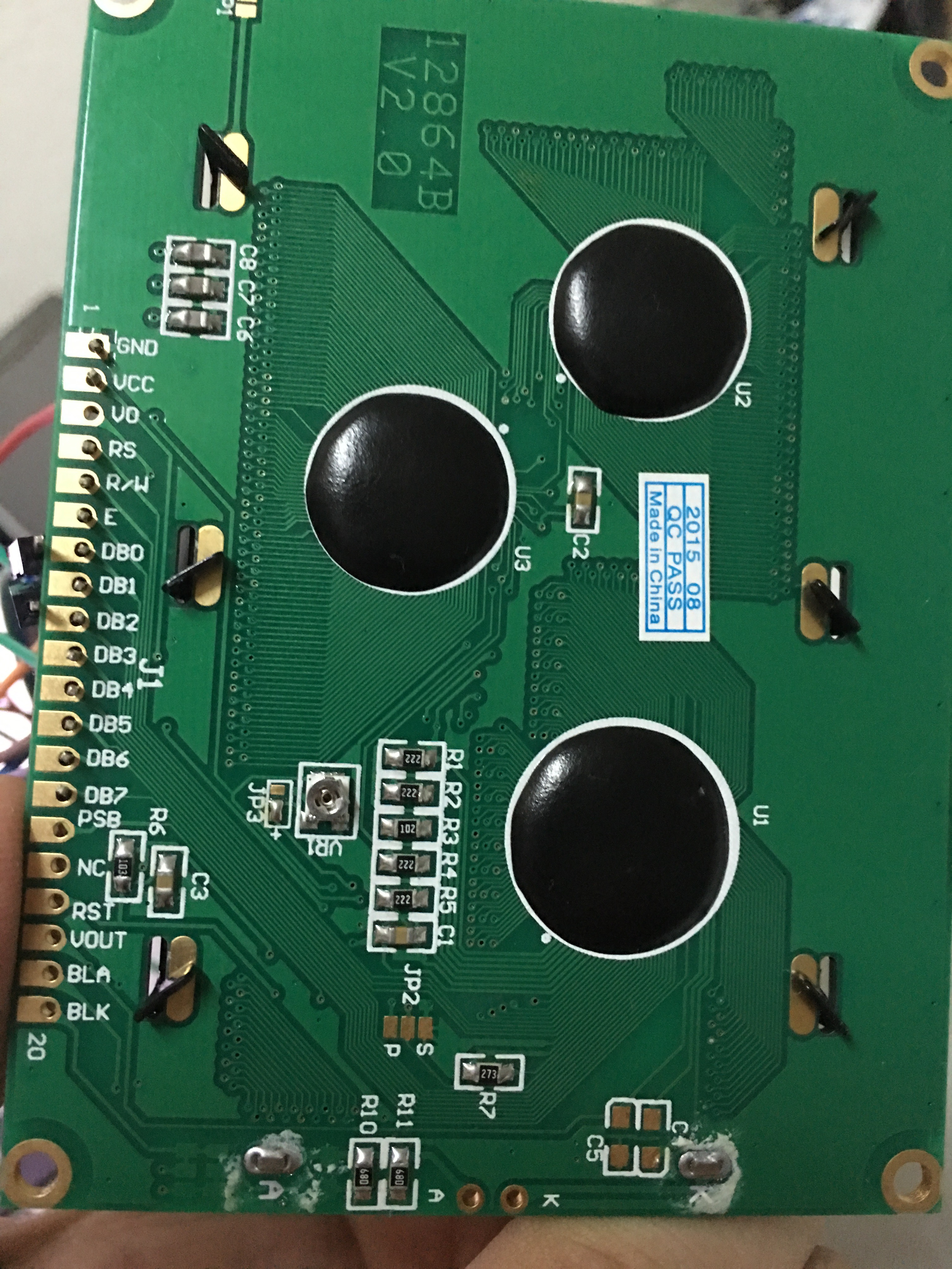
I'm trying to connect 128x64 GLCD with TM4C123G Connected Launchpad and programming with Code Composer Studio. I want to interface with my LCD by using 8-Bit Data interfacing. I am having trouble doing that. I connected

VBus to VCC

GND to GND

PA2  to RS

PA3  to RW

PA4  to EN

Below you will find my pin connections from the Stellaris Launchpad to the LCD:

tm4c123gxl Pin          PB0     PB1     PB2     PB3     PB4     PB5     PB6     PB7

--------------------------------------------------------------------------------------------------------------

LCD Pin            DB0     DB1     DB2     DB3     DB4    DB5    DB6    DB7

This is my code:

SysCtlClockSet(SYSCTL_SYSDIV_1 | SYSCTL_USE_PLL| SYSCTL_XTAL_16MHZ|SYSCTL_OSC_MAIN);


SysCtlPeripheralEnable(SYSCTL_PERIPH_GPIOA);

SysCtlPeripheralEnable(SYSCTL_PERIPH_GPIOB);

SysCtlDelay(1000000);


GPIOPinTypeGPIOOutput(GPIO_PORTB_BASE, GPIO_PIN_0 | GPIO_PIN_1| GPIO_PIN_2 | GPIO_PIN_3 | GPIO_PIN_4 | GPIO_PIN_5| GPIO_PIN_6 | GPIO_PIN_7);

GPIOPinTypeGPIOOutput(GPIO_PORTA_BASE, GPIO_PIN_2|GPIO_PIN_3|GPIO_PIN_4);


SysCtlDelay(625000)

GPIOPinWrite(GPIO_PORTA_BASE, GPIO_PIN_2 , 0x00);

SysCtlDelay(4167);

GPIOPinWrite(GPIO_PORTB_BASE, GPIO_PIN_0 | GPIO_PIN_1| GPIO_PIN_2 | GPIO_PIN_3

|GPIO_PIN_4 | GPIO_PIN_5| GPIO_PIN_6 | GPIO_PIN_7, 0xc);

SysCtlDelay(4167);

//Register Select(RS) = 0, Enable(E) = 1//

GPIOPinWrite(GPIO_PORTA_BASE, GPIO_PIN_3, 0x08);

SysCtlDelay(4167);


//Register Select(RS) = 0, Enable(E) = 0//

GPIOPinWrite(GPIO_PORTA_BASE, GPIO_PIN_3, 0x00);


SysCtlDelay(4167);


but its not working, i just need write something to LCD.

  • Hien Doan Thanh69 said:
    but its not working,

    Pity that - and pity that NO Description/Detail of "What does not work" is supplied.  Might: "Low/No or unstable contrast, or vertical or horizontal lines, or reversed characters, or broken characters ALL qualify as, Not Working?   And each demands a different means of test/correction.   Thus, "Not Working" fails - and fails badly!

    Usually a contrast voltage is required - and critical.   Your post avoids all mention of such contrast pin & required voltage.

    These Lcds require a well-followed initialization procedure - I don't see that implemented w/in your code.

    Your delay of "4167" is unlikely to require such precision.   Often it proves best/safest to provide long delays - and lessen only after, "everything works."

    Hitachi set the standard for such small, Mono, Graphic Lcds.   (HD66102 iirc)   Acquire that chip's data - initialization (both sequence & codes) should be well detailed.

    And - usually the display control chip requires "independent" raising/lowering of "E."   We note your code toggling those 2 (E & RS) "in concert" which violates set-up/hold times...

  • Hello,

    Have you tried looking on the Hitachi site for driver code for TM4C or posting in their forum to see if they might have an example or offer help?
  • One doubts that (famed) and (oft repeated) "Does Not Work" will harvest much benefit there - either!   (all of the "usual suspects" have (already) been listed - earlier - right here...)

  • Hello cb1-,

    Thank for your help, "its not working", that mean i can't turn on/off LCD, or to write command to my LCD. I try bellow this code, but again can't saw anything, the screen is still back.


    //------------------- Stellaris Launchpad System Initilization------------------//
    SysCtlClockSet(SYSCTL_SYSDIV_1 | SYSCTL_USE_PLL| SYSCTL_XTAL_16MHZ|SYSCTL_OSC_MAIN);

    SysCtlPeripheralEnable(SYSCTL_PERIPH_GPIOA);
    SysCtlPeripheralEnable(SYSCTL_PERIPH_GPIOB);

    GPIOPinTypeGPIOOutput(GPIO_PORTB_BASE, GPIO_PIN_0 | GPIO_PIN_1| GPIO_PIN_2 | GPIO_PIN_3 |
    GPIO_PIN_4 | GPIO_PIN_5| GPIO_PIN_6 | GPIO_PIN_7);
    GPIOPinTypeGPIOOutput(GPIO_PORTA_BASE, GPIO_PIN_2|GPIO_PIN_3|GPIO_PIN_4);
    //------------------End of Stellaris Launchpad System Initilization------------//

    //Wait 15 Miliseconds after LCD Power Up//
    SysCtlDelay(625000);

    //-------------------------------First LCD Command----------------------------//

    // W/R = 0
    GPIOPinWrite(GPIO_PORTA_BASE, GPIO_PIN_3, 0x00);

    // Write command to LCD. 12(Dec) = 0xc(Hex) mean turn on LCD
    GPIOPinWrite(GPIO_PORTB_BASE, GPIO_PIN_0 | GPIO_PIN_1| GPIO_PIN_2 | GPIO_PIN_3|
    GPIO_PIN_4 | GPIO_PIN_5| GPIO_PIN_6 | GPIO_PIN_7, 0xc);
    SysCtlDelay(4167);

    //Register Select (RS) = 0, Enable( E) = 1. ( Decimal) 16 = 0x10 (Hex)
    GPIOPinWrite(GPIO_PORTA_BASE, GPIO_PIN_2| GPIO_PIN_4, 0x10);
    SysCtlDelay(4167);

    //Register Select (RS) = 0, Enable( E) = 0.
    GPIOPinWrite(GPIO_PORTA_BASE, GPIO_PIN_2|GPIO_PIN_4, 0x00);
    //---------------------------End of First LCD Command------------------------//

    SysCtlDelay(4167);
    //-------------------------------First LCD Data----------------------------//

    // W/R = 0
    GPIOPinWrite(GPIO_PORTA_BASE, GPIO_PIN_3 , 0x00);

    // Write data "A" to LCD
    GPIOPinWrite(GPIO_PORTB_BASE, GPIO_PIN_0 | GPIO_PIN_1| GPIO_PIN_2 | GPIO_PIN_3|
    GPIO_PIN_4 | GPIO_PIN_5| GPIO_PIN_6 | GPIO_PIN_7, 0x41);
    SysCtlDelay(4167);

    //Register Select (RS) = 1, Enable( E) = 1.
    GPIOPinWrite(GPIO_PORTA_BASE, GPIO_PIN_2| GPIO_PIN_4, 0x14);
    SysCtlDelay(4167);

    //Register Select (RS) = 1, Enable( E) = 0.
    GPIOPinWrite(GPIO_PORTA_BASE, GPIO_PIN_2| GPIO_PIN_4, 0x4);
    //---------------------------End of First LCD Data------------------------//
  • My friend - thank you - I'll review w/in next few hours.

    Have you checked for the Contrast Pin and the proper Contrast Voltage? This is VITAL!

    Link or post the Lcd's spec - I'll tell you which pin & proper voltage to apply. CAUTION: if you apply wrong polarity or excess voltage you CAN/WILL (usually) DAMAGE your display. Display spec - s'il vous plait - merci.

    You stated that yours is a 128x64 GRAPHIC Lcd - yet you send 0x41 "A" and expect "A" to display.   It will NOT - NEVER!   Graphic displays such as yours usually display a "vertical slice" of 8 bits - you must design & develop "Pixel Representations" of each character desired.   Your 0x41 came (clearly) from a Text display - which enjoys that capability.   Again - will never/ever work here - w/Graphic Display.

    And "how" did a one line posting - mostly empty (i.e. casted you to some foreign ground) - earn a "like?"   There's a French protest saying - which I'll avoid - for now...

  • Thank for advice, i used 12864B V2.0, Driver IC: ST7920, you can see it there: thegioiic.com/.../lcd12864

    This is datasheet of ST7920: www.waveshare.com/.../ST7920.pdf
    And datasheet of ST7921: www.waveshare.com/.../ST7921.pdf

    "Pixel Representations" like this:
    static const char ASCII[][5] = {
    {
    0x7e, 0x11, 0x11, 0x11, 0x7e} // 41 A
    ,{0x7f, 0x49, 0x49, 0x49, 0x36} // 42 B
    }
    right ?

  • Hello Hien,

    Can you please connect a Logic Analyzer during the initialization stage and see if the sequence is as expected by the Panel?

    Regards
    Amit
  • Thanks for those links & for the high res. photo.

    I note the following:

    • your connections do NOT appear to be soldered.   Is that the case - and you rely upon (famed) "friction fit" for connection integrity?
    • Pin 3 "Vo" is the contrast pin - and it appears empty!   (i.e. No connection in evidence)   Note that I mentioned "bad or missing contrast voltage" and if pin 3 "is" as it appears (empty/open/floating) all of the logic analyzers in the world will not yield one pixel!

    Relying upon "friction fit" for connection is not recommended!   You must install a proper header/receptacle - or properly solder those connections.   Should the power pins (1 & 2) become (even momentarily) dislodged during operation - and voltage is applied to any other display pin - damage usually results!  Not good!

    Can you read the display manual - and identify the appropriate contrast voltage?   That's good training - as is following (all) direction.   Usually a pot is employed which enables variable voltage to be applied to the contrast pin - so that the most viewable pixel field results.

    [edit] 21:57 CST: I've opened the ST7920 control chip manual.   I've seen and (once/twice) used this chip - but (only) on a 144x32 Lcd.   And - while I've not performed an in-depth read - it does appear that this chip can accept ASCII data & produce full, legible characters - even in Chinese.   Again - I've never seen this chip used on a 64 pixel row display.

    Page 18 of ST7920 manual lists the initialization instructions.   You must get these right - often in the proper sequence & in full observance of the specified display timing.  (your MCU is many, many times faster than the display)

    What remains missing - is the Display Data sheet.   ST7920 & ST7921 are controller & lcd drivers - neither exposes what the display designer has specified for the contrast pin.  (pin 3)   That data should have been included w/the display.

    While the display is very capable - it demands great attention to detail to bring fully & properly to life - thus it violates "KISS."  (it is not simple)   I'd much prefer to see you succeed w/plain character display first - only after that learning & confidence-building - venture onto this demanding display...

    As a point of note - another (highly popular here) ran into issue w/this vendor - very recently.

    With proper contrast voltage applied to pin 3 - the pixel field should "just be visible" when the display is powered, fully & properly initialized and the "Display On" command is executed .   You've missed this guidance TWICE - please do note and correct - this time...

  • Thanks a lot, finally it working.

    It not working b/c i miss pin BLA and BLK and some reason cb1_mobile suggest.

    and now i can to print to a character to screen LCD, but it use ASCII. Ex: 0x41 = A.

    I take value from sensor and i need print it to screen LCD, Ex: i have 2.3494 and want print it to screen. How i can do it ?
  • Hien Doan Thanh69 said:
    have 2.3494 and want print it to screen

    If you (really) have a value in that format (2.3494) you may simply add 0x30 to each digit - and write that to your screen.   (i.e. 2 + 0x30 yields 0x32 which displays as "2" on screen.

    More common is the need to convert from binary to decimal - which can easily be handled by dividing the value by the appropriate, "powers of ten."   For example - if your sensor value is 12,345.67 you'd first (integer) divide by 10,000 - leaving 1 which is processed as above (add 0x30) and then subract 10,000 from 12,345.67 - yielding 2,345.67.   Now you'd divide by the next power of ten (1000) yielding 2 - and pass that onto the screen.   The process continues until the value has been fully converted.   

    There are more elegant shift/rotate methods - but for (general) "Gov't Work" this method proves adequate.

    You (still) have not described your (needed) connection to the contrast pin!  (required unless that's done internally or the display is oled - not lcd!)

  • Hi Hein !
    I'm also using the same LCD that you have used in the past. I wrote code but nothing is being written to LCD, I am unable to write something on LCD12864B V2.0. Please help me .
    here is my code


    //*****************************************************************************

    //

    // blinky.c - Simple example to blink the on-board LED.

    //

    // Copyright (c) 2013-2015 Texas Instruments Incorporated. All rights reserved.

    // Software License Agreement

    //

    // Texas Instruments (TI) is supplying this software for use solely and

    // exclusively on TI's microcontroller products. The software is owned by

    // TI and/or its suppliers, and is protected under applicable copyright

    // laws. You may not combine this software with "viral" open-source

    // software in order to form a larger program.

    //

    // THIS SOFTWARE IS PROVIDED "AS IS" AND WITH ALL FAULTS.

    // NO WARRANTIES, WHETHER EXPRESS, IMPLIED OR STATUTORY, INCLUDING, BUT

    // NOT LIMITED TO, IMPLIED WARRANTIES OF MERCHANTABILITY AND FITNESS FOR

    // A PARTICULAR PURPOSE APPLY TO THIS SOFTWARE. TI SHALL NOT, UNDER ANY

    // CIRCUMSTANCES, BE LIABLE FOR SPECIAL, INCIDENTAL, OR CONSEQUENTIAL

    // DAMAGES, FOR ANY REASON WHATSOEVER.

    //

    // This is part of revision 2.1.1.71 of the EK-TM4C1294XL Firmware Package.

    //

    //*****************************************************************************

    #include

    <stdint.h>

    #include

    "inc/tm4c1294ncpdt.h"

    #include

    <stdbool.h>

    #include

    "driverlib/sysctl.h"

    #include

    "driverlib/gpio.h"

    #include

    "inc/hw_types.h"

    #include

    "inc/hw_memmap.h"

    #include

    "driverlib/timer.h"

    #include

    "driverlib/interrupt.h"

    #include

    "driverlib/systick.h"

    #include

    "driverlib/rom.h"

    #include

    "driverlib/rom_map.h"


    //*****************************************************************************

    void

    delay(uint32_t num);

    volatile

    unsigned long long int clock,period;

    int

    main(

    void)

    {

    //Clock Set

    clock=

    SysCtlClockFreqSet((SYSCTL_XTAL_25MHZ |SYSCTL_OSC_MAIN | SYSCTL_USE_PLL |SYSCTL_CFG_VCO_480), 120000000);

    //Port Initialization-Used many ports, beacuse few pins left, i have not left any free

    //conscutive pins to connect with lcd, rest of all pins connected with sensors and other devices

    SysCtlPeripheralEnable

    (SYSCTL_PERIPH_GPION);

    SysCtlPeripheralEnable

    (SYSCTL_PERIPH_TIMER0);

    GPIOPinTypeGPIOOutput

    (GPIO_PORTN_BASE,GPIO_PIN_0);

    period=clock;

    //Port Initialization-Used many ports, beacuse few pins left, i have not left any free

    //conscutive pins to connect with lcd, rest of all pins connected with sensors and other devices

    SysCtlPeripheralEnable

    (SYSCTL_PERIPH_GPIOA);

    SysCtlPeripheralEnable

    (SYSCTL_PERIPH_GPIOH);

    SysCtlPeripheralEnable

    (SYSCTL_PERIPH_GPIOM);

    SysCtlPeripheralEnable

    (SYSCTL_PERIPH_GPIOE);

    SysCtlPeripheralEnable

    (SYSCTL_PERIPH_GPIOB);

    SysCtlPeripheralEnable

    (SYSCTL_PERIPH_GPIOK);

    SysCtlPeripheralEnable

    (SYSCTL_PERIPH_GPION);


    //DATA-SIGNALS

    GPIOPinTypeGPIOOutput

    (GPIO_PORTA_BASE,GPIO_PIN_4|GPIO_PIN_5);

    //DB0,DB1

    GPIOPinTypeGPIOOutput

    (GPIO_PORTH_BASE,GPIO_PIN_1);

    //DB2

    GPIOPinTypeGPIOOutput

    (GPIO_PORTM_BASE,GPIO_PIN_4);

    //DB3

    GPIOPinTypeGPIOOutput

    (GPIO_PORTE_BASE,GPIO_PIN_4|GPIO_PIN_5);

    //DB4&DB5

    GPIOPinTypeGPIOOutput

    (GPIO_PORTN_BASE,GPIO_PIN_4|GPIO_PIN_5);

    //DB6, DB7

    //CONTROL-SIGNALS RS, R/W AND EN

    GPIOPinTypeGPIOOutput

    (GPIO_PORTB_BASE,GPIO_PIN_4|GPIO_PIN_5);

    //RS,R/W

    GPIOPinTypeGPIOOutput

    (GPIO_PORTK_BASE,GPIO_PIN_2);

    //EN

    //RESET-RST

    GPIOPinTypeGPIOOutput

    (GPIO_PORTM_BASE,GPIO_PIN_6);

    //PSB

    GPIOPinTypeGPIOOutput

    (GPIO_PORTK_BASE,GPIO_PIN_3);

    //Reset low to high delay

    GPIOPinWrite

    (GPIO_PORTM_BASE,GPIO_PIN_6,0x00);

    //PSB- PARALLEL

    GPIOPinWrite

    (GPIO_PORTK_BASE,GPIO_PIN_3,0x8);

    delay(4800000);

    GPIOPinWrite

    (GPIO_PORTM_BASE,GPIO_PIN_6,0x20);

    //function set

    GPIOPinWrite

    (GPIO_PORTA_BASE,GPIO_PIN_4|GPIO_PIN_5,0x00);

    //DB0,DB1

    GPIOPinWrite

    (GPIO_PORTH_BASE,GPIO_PIN_1,0x00);

    //DB2

    GPIOPinWrite

    (GPIO_PORTM_BASE,GPIO_PIN_4,0x00);

    //DB3

    GPIOPinWrite

    (GPIO_PORTE_BASE,GPIO_PIN_4,0x10);

    //DB4

    GPIOPinWrite

    (GPIO_PORTE_BASE,GPIO_PIN_5,0x20);

    //DB5

    GPIOPinWrite

    (GPIO_PORTN_BASE,GPIO_PIN_4|GPIO_PIN_5,0x00);

    //DB6, DB7

    //RS/RW

    GPIOPinWrite

    (GPIO_PORTB_BASE,GPIO_PIN_4|GPIO_PIN_5,0x00);

    //RS|RW

    //EN

    GPIOPinWrite

    (GPIO_PORTK_BASE,GPIO_PIN_2,0x00);

    delay(16800);

    GPIOPinWrite

    (GPIO_PORTK_BASE,GPIO_PIN_2,0x4);

    delay(12000);

    //display-on-Off

    GPIOPinWrite

    (GPIO_PORTA_BASE,GPIO_PIN_4|GPIO_PIN_5,0);

    //DB0,DB1

    GPIOPinWrite

    (GPIO_PORTH_BASE,GPIO_PIN_1,0x00);

    //DB2

    GPIOPinWrite

    (GPIO_PORTM_BASE,GPIO_PIN_4,0x10);

    //DB3

    GPIOPinWrite

    (GPIO_PORTE_BASE,GPIO_PIN_4|GPIO_PIN_5,0x00);

    //DB4&DB5

    GPIOPinWrite

    (GPIO_PORTN_BASE,GPIO_PIN_4|GPIO_PIN_5,0x00);

    //DB6, DB7

    //rs-rw

    GPIOPinWrite

    (GPIO_PORTB_BASE,GPIO_PIN_4|GPIO_PIN_5,0x00);

    //en

    GPIOPinWrite

    (GPIO_PORTK_BASE,GPIO_PIN_2,0x00);

    SysCtlDelay

    (12000);

    GPIOPinWrite

    (GPIO_PORTK_BASE,GPIO_PIN_2,0x4);

    SysCtlDelay

    (12000);

    //display clear

    GPIOPinWrite

    (GPIO_PORTA_BASE,GPIO_PIN_4,0x10);

    //DB0

    GPIOPinWrite

    (GPIO_PORTA_BASE,GPIO_PIN_4,0x00);

    //DB1

    GPIOPinWrite

    (GPIO_PORTH_BASE,GPIO_PIN_1,0x00);

    //DB2

    GPIOPinWrite

    (GPIO_PORTM_BASE,GPIO_PIN_4,0x00);

    //DB3

    GPIOPinWrite

    (GPIO_PORTE_BASE,GPIO_PIN_4|GPIO_PIN_5,0x00);

    //DB4&DB5

    GPIOPinWrite

    (GPIO_PORTN_BASE,GPIO_PIN_4|GPIO_PIN_5,0x00);

    //DB6, DB7

    //RS-R/W

    GPIOPinWrite

    (GPIO_PORTB_BASE,GPIO_PIN_4|GPIO_PIN_5,0x00);

    //EN

    GPIOPinWrite

    (GPIO_PORTK_BASE,GPIO_PIN_2,0x00);

    delay(1200000);

    GPIOPinWrite

    (GPIO_PORTK_BASE,GPIO_PIN_2,0x4);

    SysCtlDelay

    (1200000);

    //ENTRY-MODE-SET

    GPIOPinWrite

    (GPIO_PORTA_BASE,GPIO_PIN_4,0x10);

    //DB0

    GPIOPinWrite

    (GPIO_PORTA_BASE,GPIO_PIN_5,0x20);

    //DB1

    GPIOPinWrite

    (GPIO_PORTH_BASE,GPIO_PIN_1,1);

    //DB2

    GPIOPinWrite

    (GPIO_PORTM_BASE,GPIO_PIN_4,0);

    //DB3

    GPIOPinWrite

    (GPIO_PORTE_BASE,GPIO_PIN_4|GPIO_PIN_5,0);

    //DB4&DB5

    GPIOPinWrite

    (GPIO_PORTN_BASE,GPIO_PIN_4|GPIO_PIN_5,0);

    //DB6, DB7

    //RS-R/W

    GPIOPinWrite

    (GPIO_PORTB_BASE,GPIO_PIN_4|GPIO_PIN_5,0);

    //EN

    GPIOPinWrite

    (GPIO_PORTK_BASE,GPIO_PIN_2,0);

    SysCtlDelay

    (2000000);

    GPIOPinWrite

    (GPIO_PORTK_BASE,GPIO_PIN_2,0x4);

    SysCtlDelay

    (1200000);

    //WRITING 0x41 "A" to DATA-bus DB0-DB7

    GPIOPinWrite

    (GPIO_PORTA_BASE,GPIO_PIN_4,0x10);

    //DB0

    GPIOPinWrite

    (GPIO_PORTA_BASE,GPIO_PIN_5,0);

    //DB1

    GPIOPinWrite

    (GPIO_PORTH_BASE,GPIO_PIN_1,0);

    //DB2

    GPIOPinWrite

    (GPIO_PORTM_BASE,GPIO_PIN_4,0);

    //DB3

    GPIOPinWrite

    (GPIO_PORTE_BASE,GPIO_PIN_4|GPIO_PIN_5,0);

    //DB4&DB5

    GPIOPinWrite

    (GPIO_PORTN_BASE,GPIO_PIN_4,0x10);

    //DB6,

    GPIOPinWrite

    (GPIO_PORTN_BASE,GPIO_PIN_5,0);

    //DB7

    //RS-R/W

    GPIOPinWrite

    (GPIO_PORTB_BASE,GPIO_PIN_4,0x10);

    //RS

    GPIOPinWrite

    (GPIO_PORTB_BASE,GPIO_PIN_5,0);

    //R/W

    //EN

    GPIOPinWrite

    (GPIO_PORTK_BASE,GPIO_PIN_2,0);

    SysCtlDelay

    (12000);

    GPIOPinWrite

    (GPIO_PORTK_BASE,GPIO_PIN_2,0x4);

    while

    (1){

    GPIOPinWrite(GPIO_PORTN_BASE,GPIO_PIN_0,1);

    delay(period/2);

    GPIOPinWrite(GPIO_PORTN_BASE,GPIO_PIN_0,0);

    delay(period/2);

    }

    }

    void

    delay(uint32_tnum){

    TimerIntClear(TIMER0_BASE,TIMER_TIMA_TIMEOUT);

    TimerConfigure(TIMER0_BASE,TIMER_CFG_PERIODIC);

    TimerLoadSet(TIMER0_BASE,TIMER_A,num-1);

    // TimerIntEnable(TIMER0_BASE, TIMER_TIMA_TIMEOUT);

    TimerEnable(TIMER0_BASE, TIMER_A);

    while(!TimerIntStatus(TIMER0_BASE,false)){

    }

    }


    Regards
    Haroon