This thread has been locked.

If you have a related question, please click the "Ask a related question" button in the top right corner. The newly created question will be automatically linked to this question.

Writing integer values to GPIO DATA registers

Other Parts Discussed in Thread: TM4C123GH6PM

Greetings, denizens of the e2e community.

I am programming a TM4C123GH6PM microcontroller within a TIVA Launchpad using Code Composer Studio. What I am doing is generating variable pulse widths with the GPIOs using interrupts that are triggered when a general purpose timer count reaches 0. Within this interrupt, the next pulse width duration in the lookup table is loaded into the timer using the Tivaware API, as is the 'high' or 'low' value for the GPIO to take, corresponding to its timer duration. 

Speed is very important in this application and unfortunately, the necessary timer reconfiguration during the interrupt takes up a lot of time, which adds considerably to the minimum pulse width it can generate. The minimum pulse width it can generate right now is about 1.4 microseconds. In order to speed it up I have used direct register access to disable and enable the timer for reconfiguration during the interrupt which shaved off about 400 nanoseconds, so before, using just Tivaware API functions, the minimum pulse width it could generate was about 1.8 microseconds. If I can get this down to about 1 microsecond, I would be satisfied. And i think this can be achieved through direct register access writing to the data register of the GPIO and the timer load register, instead of using the Tivaware API. So my question is this:

I have two arrays, one of type uint8_t and the other uint32_t. The uint8_t array is filled with the desired 1 and 0 values for the GPIO data register and the uint32_t array is filled with the desired timer load values, corresponding to each of the GPIO output values stored in the uin8_t array.

How do I write these values to the GPIO data and timer load registers? I tried just doing something like this:

GPIO_PORTF_DATA_R = switchingVectors[interruptCounter];

But when I try to run it, I get a faultISR.

So obviously, my understanding is lacking here. Could anyone enlighten me as to how to do this?

  • Are you aware that most GPIO Ports have both HIGH & normal speed toggle modes? "AHB" bus - w/in your MCU manual - should detail.

    I'd suspect that the simple switch to the high-speed bus would meet your, "about 1µS" objective...
  • Ah yes. I was but I had completely forgotten to try it. I will try this and see how much it improves.
  • Oops no, turns out I have actually already configured the GPIOs to use the AHB.
  • Sorry about that - twas the "easiest" way to increase speed.

    Did you verify that toggle speed did increase via AHB bus? It is possible - though unlikely - that the bus switch was not entirely successful...
  • Joshua Lowry said:
    GPIO_PORTF_DATA_R = switchingVectors[interruptCounter]; 

    Has been ages since firm/I have used DRM w/this vendor's MCUs.   Is "GPIO_PORTF_DATA_R" a valid label?   If you code:

    GPIO_PORTF_DATA_R = 0xAB; do the Port_F pins assume the correct values?   If so - then the right-side of your assignment causes your fault.

    Might it be that you require "two steps:" first to extract the GPIO or Timer Load Value from the related array; and second to present that byte or word to the GPIO Data or Timer Load Register?

    You're close - I'd bet that bit more experimentation will see you reach your goal...

  • Hello Joshua

    A timer in PWM mode would perform the same task of generating variable length 1's!!!

    Regards
    Amit
  • Amit, I think he's driving multiple outputs at the same time. If it's, in fact, only a single output then SPI might be a better alternative.

    I've another thought, is switchingVectors a uint8_t? If so you should try it as uint32_t. There are a couple of reasons to consider this
    The port you are writing to is actually a 32 bit write IIRC, and the memory is organized as 32 bits with the processor shifting and masking as needed. The masking, shifting and expansion may be masked in the bus access but it's probably worth a quick check.

    Finally this is an issue where the low latency of DMA might actually be useful. It might require some detailed thought in design to get that to work though, if it turns out to be possible.

    Robert
  • Hello Robert,

    Yes, if it is a case of driving multiple outputs then using multiple timers would be a waste of resource. In this case the user has mentioned that the FaultISR is being invoked. What the user has failed to mention is which Fault bits are being set.

    If it is a case of alignment, then the alignment access error bit in the FAULTSTAT must be set.

    Regards
    Amit
  • Yes, I had overlooked the fault I was just considering speed. There's nothing obviously wrong with that assignment code. Both the lvalue and rvalues should have the correct type for their use and the compiler should take care of correcting the size and access properly.

    GCC did have an issue where it would do byte accesses to word variables under some circumstances as an optimization but he's not using GCC and I don't think that particular corner condition applies here in any case.

    Maybe the fault comes from some change made at the same time as the change to an array assignment?

    Robert

  • Hello Robert,

    I believe the poster needs to present the code and not just the assignment alone.

    Regards
    Amit
  • Hello cb1. I tried doing this and it caused another fault. I quickly realised that since i had configured the microcontroller to use the AHB, GPIO_PORTF_DATA_R was not the correct label as that uses the normal speed bus. The correct label was "GPIO_PORTF_AHB_DATA_R". Once I changed this, it worked as expected. What the fault i was previously experiencing got me thinking was that values of type int were somehow not directly compatible with the registers, which confused me because it flew in the face of my understanding of how int values are represented.

    Thank you for your help, and thank you to everyone else for taking the time to post their suggestions.
  • I will look into this as well. Thank you for letting me know.
  • Good for you - and do note that, "You Alone!" noted that issue!

    Might you present a comparison tabulation of your results - ideally (don't hate me) comparing/contrasting:

    • execution time via the API & standard (APB bus)
    • execution time via the API & faster (AHB bus)
    • execution time via DRM & faster (AHB bus)

    There IS a "time/place" for DRM and perhaps such a tabulation will better provide insight to your (always interested) forum "crue"...

  • Yes of course! This will also benefit me as I can talk about this in my report later as this is for my university Master's project. I would share the source code as well, but it will be going into my project report and if I put it on here, it will undoubtedly show up on the university plagiarism filters and I don't want problems with this later on.

    So when initialising the array holding the timer load values, I simply made every element equal to zero such that, when the timer is re-enabled at the end of the interrupt handler, having already been loaded with a starting count value of 0, it will already be at 0 and therefore immediately generate the interrupt so that the same interrupt handler runs again. I also put alternating 1's and 0's into the GPIO output value array, so that it outputs a regular square waveform. I also made sure not to include any unnecessary extra API or Direct Register writes when obtaining the results. Just the bear essentials. I measured the pulse widths with a GW Instek oscilloscope. So:

    Within the interrupt handler in each experiment in the following order:

    -cleared the timer interrupt so that it no longer asserts.
    -Disabled the timer.
    -incremented interrupt counter variable.
    -loaded timer value
    -wrote the desired pin output
    -enabled timer

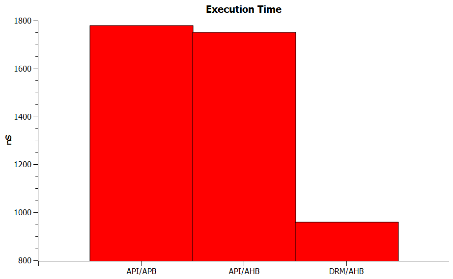
    Execution time via API and APB bus is 1780ns.
    Execution time via API and AHB bus is 1750ns.
    Execution time via DRM and AHB bus is 960ns.
  • Thanks much - appreciated.

    Agree that your display of resourcefulness in "Squeezing out performance" will prove of interest & value to your university project.  

    Earlier Amit thought that you were focused upon "one single GPIO."   That's still unclear (at least to me) and as your timer "reverses" each GPIO bit - does that not yield a (potential) or (realized) full port (8 bit here) toggle?    And - should you load different (strategic) GPIO values w/each timer update - more complex waveforms are possible.

    Now I have some trouble in accepting (just) a 30nS improvement - realized by shift from "APB to AHB."   When firm/I have past done that - the improvement was substantially larger.    I stand guilty of not (past) asking you to "better define" just what's measured during that, "Execution Time."  Might you better detail that - for all here - now?   Along those lines - might this prove a proper measure:

    • Start your elapsed timer (perhaps marked by a GPIO toggle) with the timer's trigger
    • Halt that elapsed timer upon the toggle of the GPIO bit(s).
    • Without use of a (time adding loop) repeat (cascade) your code sequence so that perhaps 3-5 complete operations are transacted.

    I'd wager a (tall) stack of chips that "APB to AHB" will vastly exceed the 30/1780 speed improvement - earlier (but undefined) noted...

    Thanks again for sharing that deemed appropriate - it's especially nice when those "helped" transform into skilled "helpers."

  • Agreed thanks,

    I'm a little surprised that a master's thesis is run through an automated plagiarism filter but I suppose once it's paid for... I just would have thought that assurance to be the job of the advisor and committee.  However, different systems for different places and I've been away from that for some time.

    So as a visual indicator see the following (side note, apparently the forum can't deal with SVG images)

    Robert